0

I wanted to operate remotely a motor which is controlled by a manual key switch (still in place in case the automated way fails - which happened).

The switch: Switch - side Switch - back

I though by replacing it by basics relay commanded by wifi would have suit the need. I used sonoff 4ch pro r2 board with the following relays: Sonoff 4ch pro r2 relays
Even if the rating is different I thought I would give it a try - at worst the relay die and I change it to suits the same rating as the initial key switch.

However the replacement did not failed where I expected it initially.

Again, the idea was to mimic the work of the manual key switch.

The motor board has (4 inputs: +24VDC, GND, CMD CW clockwise, CMD CCW counterclockwise) CMD CW and CMD CCW are set to +24VDC to instruct the motor. The relays (RLY1 & RLY2) of the sonoff card is sending the +24VDC to the right CMD. Hardware exclusion makes it impossible to have CMD CW and CMD CCW up at the same time:

Overall powering

I powered the board with the same line as the motor. I knew it was risky because the voltage on this line has a motor on it. But still, it worked quite well for a long time.

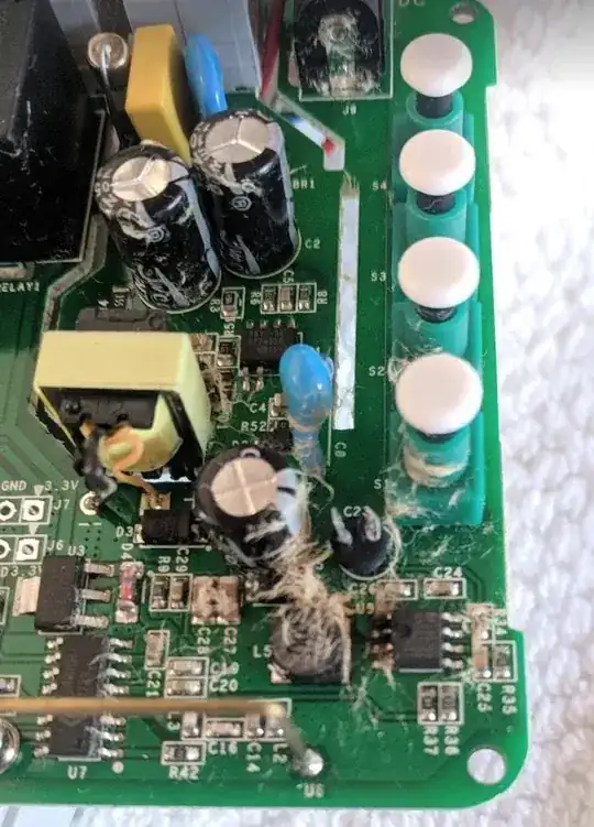
I was just finishing to pair the sonoff with a rf433 when I started to test the motor and the C23 starting to fumes.

From my basic understanding: C23 (45uF 35V) is there to absorb small voltage fluctuation. It burned A: because the voltage was too high or B: voltage was negative.

Q1: Is there a chance that only the C23 is to replace ? Or should I start to think to change voltage regulator MP2307DN too ? This is SOC so I think it will be quite difficult for my level of soldering.

Q2: Should I think to change the capacitor and the regulator by something different to ensure protection or how can I protect the circuit from surges and ensure this will never happen again ?
Sonoff 4ch pro schematic

MP2307DN voltage regulator datasheet

The result ...

user1707414
  • 111
  • 2
  • Did you manage to resolve this? I have a similar issue with blown C23 but as in your image it looks like the U9 IC to the right is damaged on pin2. Do you know what this IC is and did it also need to be replaced? – Mike Jun 12 '20 at 11:26

2 Answers2

1

Put a diode in series with the 24 volt feed to the sonoff module so, should the motor decide to draw excessive currents, it doesn't try and extract that current from C23. That could be one reason.

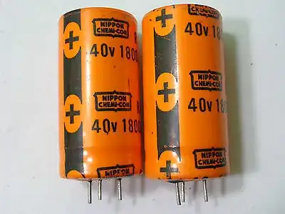
The other candidate is that you allowed the motor to put braking energy onto the 24 volt line and destroyed the capacitor due to over-voltage. This would require a fix that uses a bulk electrolytic capacitor in parallel with the 24 v DC motor terminals so that it (the added capacitor) took the brunt of the energy during braking.

However, if you don't dissipate that energy the voltage could creep up so I would be considering adding a voltage regulator to feed the sonoff module.

Of course, you may just have been unlucky and C23 was going to fail anyway.

Andy aka
  • 434,556
  • 28
  • 351
  • 777
  • Thanks, I will draw the diagram your are suggesting. I got the diode, the bulk electrolytic capacitor but not sure about the voltage regulator. What would be the characteristic of it ? – user1707414 Jun 14 '18 at 19:48
  • I'm not sure what the lowest voltage that the sonoff can run from. If it can run from 18 volts and draws only about 100 mA then use a 7812. If it needs more than 100 mA you'll need a heatsink else use a buck regulator. I'm not familiar with the sonoff. – Andy aka Jun 14 '18 at 21:19
  • Would it not be a duplicate as the sonoff already has a mp2307dn for voltage regulation ? I had a look on a tvs diode to avoid surge on the protected circuit. Or would the electrolytic capacitor in parallel would be sufficient to store the energy ? What size should I take ? – user1707414 Jun 14 '18 at 21:48
  • The mp2307dn is only rated to a supply voltage of 26 volts maximum so it is a potential weak spot. I cannot tell you how much energy could be required to be stored - you need to investigate this and possibly use a capacitor and a TVS but I think you do need a regulator capable of 40 volts at the input just in case. – Andy aka Jun 15 '18 at 08:40
1

Update:

Consider Motor snubbers (plastic caps) across motor depending on motor 1uF to 10uF rated for motor current, increase V rating on e-caps >+50V onboard. Add diode supply protection. ( some EE's will choose based on L/R and L/C to optimize) Since this is high current low voltage the C values shown below should be in the 1~10uF range vs 0.1uF.

Test and verify results with current and voltage sense on all interfaces.

enter image description here This is what happens when design without full interface specs . You don’t think about backEMF, EMI , intermittent Loss of radio data, valid signal levels vs fault levels and protection for every failure mode, component stress levels , design margin

  • Snubber for forward brake. FWD off
  • same for reverse

Without this motor switching on and off rapidly dumps far energy than steady state due to motor release acting as a generator now applying 24V while other coils in opposite direction draw now 20x at full speed of rate current trying to go in the opposite direction .

There are too many system level system faults in this design to mention in spite of your limited “success”.

Note the slight outgassing bulge in cap upper left corner .

If you don’t think about the function and failure modes now, on each line I guarantee you find a dozen more flaws from RF interruptions.

The hardware XOR of Fwd/Rev is inadequate . When storing energy in the motor as kinetic energy , it must be controlled. I hope your Relays are rated for 10x steady state and high voltage arcs. This is not a great way to control motors when there are so many cheap Chinese products that even though may be “poor” quality are better choice to study (reverse engineer) and learn before you DIY . But I understand you are keen and need encouragement , Diode blocking , snubbers Code sanity checking , fault detection , location and recovery defined before you can design it. Plus more experience in thermo electrical impedance stresses and MOSFET vs Relay design choices are not trivial with arcing on contacts (bad) but if the low side voltage is released first the high side gets 48V on C24.

Even though you may have gotten a few hundred things right in your design , it’s identifying potentials failures in design with detailed specs for fault , fit , function , margin and tolerance that make a designer achieve success. The motor should be PWM voltage ramp controlled for acceleration and braking with an RdsOn << DCR of motor with dead time using controlled acceleration , velocity wait time in a smooth servo -like function.

Study (Reverse Eng) designs by Hitachi, Fuji, Yamaha even old consumer DVD drives etc to learn how everything is done precisely and how every part serves many functions.

Tony Stewart EE75
  • 1
  • 3
  • 54
  • 182
  • Thank you very much for the in-depth explanation. I will need time to digest it all. I added an explanation by editing the initial post to show why I choose this. Basically the complex part seems already managed by the motor board. I just wanted to replace the manual switch. Therefore is your comments still valid ? – user1707414 Jun 14 '18 at 19:37
  • Ok static infrequently toggled switch . Is it center Off? Was the switch your choice too? If so what motor and load? Or part of reliable system . Yes review fault of reversing direction is far greater power than wait to stop. – Tony Stewart EE75 Jun 14 '18 at 19:53
  • Yes center OFF. The switch was already on the reliable system. About the "reversing direction" would it be correct to say that if the rly1 is on, goes off, and rly2 goes on quickly then the 24V line could surge ? – user1707414 Jun 14 '18 at 21:50
  • Starting motor has no surge. Stopping motor by open circuit ( for ANY moving contact) creates inductive arc across contacts at high contact temp. Consider Motor snubbers (plastic caps) across contacts. – Tony Stewart EE75 Jun 15 '18 at 01:40