1

Edit: solution found

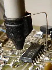
There was some amount of flux residue remaining on the board from when I soldered it. My meter didn't beep in continuity mode, but it did register some resistance, which I didn't notice at the time of soldering because I was only listening for a beep and not watching the meter.

The boards were throughly cleaned with a brush and 100% isopropyl, then checked for continuity between the pins which showed no continuity.


I'm testing a new ULN2003 module I bought with some arduino code. I have it setup as follows to a led for testing purposes.

I have noticed that when pin 1 is connected to a high signal (5v), pin 16 allows for current flow, and the attached LED is turned on, this is expected.

However, while pin 1 is high, and pin 2 is low (GND) the collector on pin 15 is allowing some small amount of current flow, enough to dimly light the attached LED.

Is this the correct behavior of the ULN2003 chip, or am I doing something incorrectly?

enter image description here

Its difficult to see in this photo, but the LED connected to pin 15 is dimly lit, if I switch pin 1 to gnd and pin 2 to 5v, led 2 is fully lit, and led 1 is dimly lit. Here is a photo of how I have the circuit connected
MKUltra
  • 147
  • 1
  • 8
  • Are you bread-boarding this, or using a blank PCB?. The outputs are OC Darlingtons with internal pull-down resistors, so this should not be happening. –  Jun 13 '18 at 21:34

2 Answers2

2

I suspect you soldered the ULN2003 to the board using solder that is not electronic grade solder so the flux residue is conductive (and also very corrosive). If so. Try cleaning the board throughly.

Spehro Pefhany
  • 376,485
  • 21
  • 320
  • 842
  • I remember cleaning the board with 100% isopropol when I soldered it, and I checked for continuity, I'll rewash one of the boards and check again. – MKUltra Jun 13 '18 at 22:20
  • 1
    Well, seems that this was the problem. I cleaned both boards with 100% and a brush, and the module is now working as expected. I must have not cleaned it well enough. I'll keep this in mind for future projects! – MKUltra Jun 13 '18 at 22:29
  • 1
    Please throw that solder out or put it in with the plumbing supplies, if you think the problems you had were bad, you should see what it does at mains voltages. Not pretty – Spehro Pefhany Jun 13 '18 at 22:50
1

enter image description here

Figure 1. The ULN2003 pinout and internal configuration.

Something is not right. With the IN pin grounded the Darlington transistors should be fully off. The base pull-down resistors help to ensure that even if IN is left floating.

Post a photo of your layout and we might spot something.


Its difficult to see in this photo, but the LED connected to pin 15 is dimly lit, if I switch pin 1 to GND and pin 2 to 5 V, LED 2 is fully lit, and LED 1 is dimly lit.

Check the silly stuff first. Is there any chance that you are getting sideways spill from the LED that's on? Put a piece of opaque card or plastic between them and see if the dim LED goes out.

Transistor
  • 168,990
  • 12
  • 186
  • 385
  • I posted a photo of my circuit. – MKUltra Jun 13 '18 at 21:52
  • See the update. – Transistor Jun 13 '18 at 21:58
  • I previously had them separated by a few inches, I moved them closer for visibility in the picture. I tried 2 different uln2003 modules, both produce the same behavior. – MKUltra Jun 13 '18 at 22:02
  • Measure the voltage between your power-supply ground and pin 8 on the module to check that it's connected properly. It should read 0 V. Do the same with +5 to pin 9 (but it's unlikely to cause this problem). – Transistor Jun 13 '18 at 22:04
  • Checked, both show as 0 on my meter, I did notice that the unconnected pins (3 - 7) are floating around 60-70mv. – MKUltra Jun 13 '18 at 22:11