For a simple AM, we multiply a low frequency message signal ( \$\sin(t)\$) with a high frequency carrier (\$\sin(10^6t)\$) to produce two high frequency signals :
$$\sin(t)*\sin(10^6t) = \dfrac{1}{2}\left(\cos[(10^6+1)t] + \cos[(10^6-1)t] \right)$$
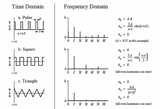
I'm hoping there exists a similar formula when we do PWM, but wiki and other sources talk about many other things except a formula like above. So I'm posting this question here. How to represent the output of the comparator waveform mathematically ? Like, the input modulating signal is \$\sin(t)\$, and the input triangular waveform may be some piecewise linear function ? Then what will be the expression for the comparator output ? I mean exactly what frequencies does the output contain ?

