2

I am designing a single cell Li-Po charger with a PIC. I have this:

enter image description here

I drive the transistors from a 12F PIC microcontroller. As you can see in the square wave on the top of the oscilloscope the signal is not falling to 0V, it falls to 1.85V and the highest voltage it reaches is 5V so I have 5-1.85 = 3.15V on the battery and I need 4.2V to charge it.

Why the voltage is not reaching 0V ? I have tried whit a 2N7000 Mosfet but driving it at 5V provides too much Rds resistance and voltage reaches 5V but falls to about 4V only. Is there any other solution you can think in ?

R1 is suppose to be the battery draining 500 mA as much (USB limit) and R3 is used for current sense.

Thank you !

Andres
  • 1,834
  • 4
  • 31
  • 51

1 Answers1

3

Warning:

  • When you modify the circuit as described below so that it works "properly" it will try to destroy a LiPo battery. This is because you are applying 5V to the battery when you should only apply 4.2V absolute maximum.

    With R1 = 5 ohms you will be able to supply about 150 mA at 4.4V and about 100 mA at 4.4V. This is well outside the safe spec of essentially all LiPo batteries that you will use and a "vent with flame" incident is a possibility.

    Your design needs to ensure that the voltage applied to the battery does not ever exceed 4.2V. You can PWM switch a higher voltage to reduce it to 4.2V max if you filter the PWM so the battery never sees a voltage above 4.2V. If you eg PWM switched 5V at 84% duty cycle the mean level would be 0.84 x 5V = 4.2V. But, if you applied this PWM signal to the battery directly the 5V peak level would be likely to cause damage.

    LiPo charging ICs are readily available at a reasonable cost. You are liable to be better off using one.

    Relying on the USB port to limit current is an invitation to flaming destruction of your battery, or more. While a port may be specified to deliver 500 mA to one USB socket, it may be capable of supplying several amps in some cases. That plus over voltage on the battery is a formula for fireworks.


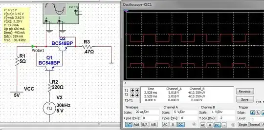
The problem with the existing circuit:

Q1 & Q2 form a "Darlington pair". The output voltage cannot be more than 2 x Vbe drops below V2 as each base emitter junction must drop Vbe of about 0.6 Volt for the transistor to turn on.

V2 = 5V
Q1e = 5-0.6 = 4.4V
Q2e = Q1e -0.6 = 4.4 - 0.6 = 3.8V. In practice you are getting somewhat less due to higher Vbe values.

A solution is to replace Q1 and Q2 with a PNP transistor (call it Q3) with emitter to R1, collector to R3 and drive the base via R2. Now the transistor will be on when V2 is low. Or you can use a P Channel MOSFET with source to R1, drain to R3 and gate to V2.
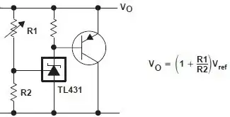

Voltage limiter:

If building your own charger, you need to limit maximum battery voltage.
My answer here shows how to build a low cost precision clamp circuit to limit battery voltage.

Adjustable voltage clamp - see reference above for details.

enter image description here


As an indication of how simple an IC based charger can be, as lonhg as you can obtain the ICs, then if you want to build your own Lithium Ion / LiPo charger for up to 500 mA charge rate then using the MCP83831 / MCP83832 charger IC is a very easy and economical way of doing so. Data sheet here

It can literally be as simple as this circuit
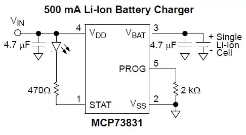
enter image description here.

For more details on this see my answer to this stack exchange question.

The ICs are available in stock from Digikey for $US0.68/1 and $US0.42/100.

Russell McMahon
  • 147,325
  • 18
  • 210
  • 386
  • Thank you for the answer :) The 5 Ohm resistor is only for simulating a 500mA current which will be the maximum that can be drain from USB. About 5V, are you sure it will damage the battery ? Because I am switching GND connection so the voltage should be Vmax * sqrt(duty[%]) so at 5V and 50% duty I have 3.53V or I have to switch the 5V source instead of GND? I would buy a Li-Po charger , single cell are very cheap but they are not sold here I have to buy it from EEUU for example (I am from Argentina) :/ – Andres Aug 14 '12 at 01:11
  • If I have no choice I think I will have to pay a little more an buy from US. Before that, I have tested using PNP and PNP darlington and I get 4.1V, there is no way to get more voltage ? – Andres Aug 14 '12 at 03:31
  • @Andres - Did you do what I suggested and change your circuit. If you read my decsription carefilly and follow what volatge is where and why, as I explain,then you will see that your circuit is fundamentally unsuitable for the job you are trying to do. If you implement what I suggested it will work. If you keep using the circuit that you have now it will never work properly. [I could make a circuit something like yours work by using an FET with special characteristics, but the cct I suggested will work with "everyday" parts. – Russell McMahon Aug 14 '12 at 07:51
  • Sorry I didn't try that circuit because I thought it was only a voltage limiter and the recommendation you gave me was to use a PNP, sorry the misunderstood. I don't understand the circuit, Vo is the output voltage and the other rail is Ground or 5v? – Andres Aug 14 '12 at 15:21
  • Your existing circuit will not work with two transistors. It MAY work marginally with one transistor BUT is not designable. SO Use the PNP circuit I described. THEN use a series R. Then use the clamp circuit. Clamp without series R will fry. Ct can be modified so clamp turns off PNP when Vout is at max. BUT try PNP 1st. Go from there. – Russell McMahon Aug 14 '12 at 16:13
  • I tried whit PNP, I could reach 4.7V at 500mA whit BD140 without current sensing resistor and 4.4V whit current sensing resistor. It should be ok, thank you for your help and pacience. I don't need voltage limiter because my microcontroller makes sure voltage never exceeds 4.2V whit PWM and current never excceeds 500 mA. – Andres Aug 14 '12 at 17:13