0

enter image description hereenter image description here

In the following circuit Ic must be found.

I begun by open-circuiting the 3 capacitors, and finding the voltage at the base which is 2.5V (from the voltage divider). By assuming that Vbe=0.7V it's easy to progress, however no such thing is stated (the only data given is that β is very large), so i was wondering if there is a way to find Ic without that assumption.

If we do assume that Vbe=0.7V, then when is the Ic=Is*e(Vbe/Vt) formula used?

Manouil
  • 39
  • 9
  • *"however no such thing is stated"* - what do you mean? – Andy aka Jun 03 '18 at 18:46
  • The data given for the exercise dont include that info. – Manouil Jun 03 '18 at 18:50
  • It might be clearer if you provided the full detail of the exercise rather than feeding snippets. – Andy aka Jun 03 '18 at 18:51
  • I uploaded the full picture. – Manouil Jun 03 '18 at 18:55
  • 2
    Read this https://electronics.stackexchange.com/questions/337010/why-is-it-possible-to-replace-part-of-a-bjt-circuit-with-thevenin-equivalent/337018#337018 – G36 Jun 03 '18 at 19:01
  • And if you want to include Ic=Is*e(Vbe/Vt) formula. you need to learn first how to solve nonlinear equations. https://en.wikipedia.org/wiki/Diode_modelling#Iterative_solution – G36 Jun 03 '18 at 19:03
  • Also, it is almost to know the exact value for Vbe. Typical we assume Vbe = 0.6V...0.7V in hand calculations. But the error is not big if Vcc>>Vbe – G36 Jun 03 '18 at 19:08
  • @G36 So Vbe isn't 2.5V since the second 100k resistor is in parallel with part of the bjt and the Re (or the load draws some current as they say). About the Vbe part,so is it implied thet Vbe~.7V since the BJT is in active mode? – Manouil Jun 03 '18 at 19:21
  • Yep. Vbe is not equal to 2.5V. Even without Re resistor voltage at the base terminal won't be larger than 0.7V – G36 Jun 03 '18 at 19:43
  • you mean larger than 0.7V + Ve? – Manouil Jun 03 '18 at 19:50
  • Also, for α=1 which means Ib=0 we do in fact have a Voltage divider, dont we? – Manouil Jun 03 '18 at 19:53
  • 1
    Yes - assuming Ib=0 you can use the simple voltage divider formula. Hence, the voltage at the base node is simply 2.5 volts. As shown in my detailed answer, such a simplification is allowed only because of the negative feedback effect of RE. Such negative feedback always reduces the sensitivity of gain stages against simplifications (in your case: Ib=0 and Vbe=0,7V). Because of these simplifications you do not need the exponential relationship between Ic and Vbe which would require the knowledge of the exact VBE value, – LvW Jun 04 '18 at 06:54

2 Answers2

3

In the enclosed figure (first diagram) it is shown how an emitter resistor RE stabilizes the operating point against uncertainties of VBE. Hence, it is common practice to assume for VBE a suitable value between 0.6 and 0.7 volts because such a relatively large VBE uncertainty results only in small Ic variations (for sufficient RE-feedback).

The dotted line (vertical) shows how RE=0 (no feedback) would result in an unacceptable large Ic variation (uncerainty).

enter image description here

LvW
  • 24,857
  • 2
  • 23
  • 52
2

By assuming that Vbe=0.7V it's easy to progress, however no such thing is stated (the only data given is that β is very large), so i was wondering if there is a way to find Ic without that assumption.

Sure. Let's solve it for the general case, assuming active mode operation and ignoring the Early effect:

schematic

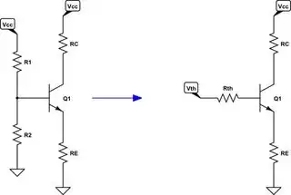
simulate this circuit – Schematic created using CircuitLab

From KVL, you have:

$$V_\text{TH}-I_\text{B}\:R_\text{TH}-V_\text{BE}-I_\text{E}\:R_\text{E}=0\:\text{V}$$

Where, of course, \$R_\text{TH}=\frac{R_1\:R_2}{R_1+R_2}\$ and \$V_\text{TH}=V_\text{CC}\:\frac{R_2}{R_1+R_2}\$.

From \$I_\text{E}=\left(\beta+1\right)\:I_\text{B}\$, you can substitute in and solve for \$I_\text{B}\$:

$$I_\text{B}=\frac{V_\text{TH}-V_\text{BE}}{R_\text{TH}+\left(\beta+1\right)\:R_\text{E}}$$

Now substitute from your nice formula and solve for \$V_\text{BE}\$:

$$\begin{align*} \frac{I_\text{SAT}}{\beta}\:e^{\frac{V_\text{BE}}{V_T}}&=\frac{V_\text{TH}-V_\text{BE}}{R_\text{TH}+\left(\beta+1\right)\:R_\text{E}}\\\\ \frac{V_\text{TH}-V_\text{BE}}{V_T}\:e^{\frac{-V_\text{BE}}{V_T}}&=\frac{I_\text{SAT}\left[R_\text{TH}+\left(\beta+1\right)\:R_\text{E}\right]}{\beta\:V_T}\\\\ \frac{V_\text{TH}-V_\text{BE}}{V_T}\:e^{\frac{V_\text{TH}-V_\text{BE}}{V_T}}&=\frac{I_\text{SAT}\left[R_\text{TH}+\left(\beta+1\right)\:R_\text{E}\right]}{\beta\:V_T}\:e^\frac{V_\text{TH}}{V_T}\\\\ \frac{V_\text{TH}-V_\text{BE}}{V_T}&=\mathcal{LambertW}\left(\frac{I_\text{SAT}\left[R_\text{TH}+\left(\beta+1\right)\:R_\text{E}\right]}{\beta\:V_T}\:e^\frac{V_\text{TH}}{V_T}\right)\\\\ V_\text{BE}&=V_\text{TH}-V_T\:\mathcal{LambertW}\left(\frac{I_\text{SAT}\left[R_\text{TH}+\left(\beta+1\right)\:R_\text{E}\right]}{\beta\:V_T}\:e^\frac{V_\text{TH}}{V_T}\right) \end{align*}$$

Note that no assumptions were made about \$V_\text{BE}\$ above. None are needed. Just as you thought might be the case! (Also note when \$u\:e^u=z\$ then \$u=\mathcal{LambertW}\left[z\right]\$. See Lambert W Function.)


This technique works over 3-5 orders of magnitude, with modest error bounds over part variations over that range; takes into account circuit details in the process for a direct solution; and it's not complicated to develop a practical value for the saturation current by looking at a datasheet; as I demonstrate here. The general solution here simply works better than the assumption and gets you a more accurate answer, and with far less effort, than alternatives.

jonk
  • 77,059
  • 6
  • 73
  • 185
  • Jonk, I think, you only have shifted the problem from Vbe (assumption necessary) to Isat (assumption necessary). Do you really think that a guess of Isat is easier than a guess of Vbe ? For my opinion, a calculation of Ic starting with an assumption for Vbe (instead of Isat=....) is (a) much more simpler and (b) exact enough because of strong DC negative feedback which makes the calculation rather insensitive to assumption uncertainties. – LvW Jun 04 '18 at 06:36
  • @LvW If you test the function with a range of values (and you can get the value pretty easily from most datasheets -- I've explained how, recently, on a [different post](https://electronics.stackexchange.com/questions/374083/how-to-derive-the-precise-gain-of-an-npn-common-emitter-amplifier-without-emitte/374089#374089)) you'll find it is better than the assumption and far more widely useful (much larger dynamic range) this way. So yes, I think it improves the situation. – jonk Jun 04 '18 at 13:06
  • as far as I have understood, the questioner needs the value of Ic for a given gain stage. However, you have proposed a method which needs prior knowledge of Ic (see the graph in your link as given with "different post") - as an input for the given formula Vbe=f(Isat). More than that, this formula contains the current gain beta which has very large tolerances. So - I cannot see how this method "improves he situation". Did I misunderstand something? – LvW Jun 04 '18 at 15:05