-2

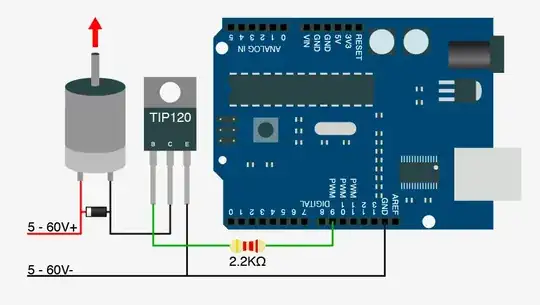
I know it must be a silly question to ask but I’m very new at electronics and I didn't knew if it is gonna work or not. Please take a look at the positive input volts in the diagram what I want to ask is are these two ways are equal? Is my diode going to work no matter what method I use and is this the correct method to put the diode to protect the transistor from reverse current?

one way is this

another way is this

And secondly please take a look at the schematics below and let me know if there is anything wrong, as I feel like if I have put excessive number of resistance on my circuit. I know you are gonna say that I’m using TIP120 in picture and FDP7030BL in schematics, well the picture was downloaded from internet and the schematics are from my real circuit planning.
enter image description here

winny
  • 13,064
  • 6
  • 46
  • 63
ZBT248
  • 19
  • 2
  • 10
  • Oh... it took me a while to get what difference you are talking about :D Yes, it's same thing. – Maple Jun 02 '18 at 23:30
  • @Maple thank you so much for your time, and is it absolutely necessary to put a resistance between signal and the base/gate of transistor? – ZBT248 Jun 02 '18 at 23:31
  • Only if you don't want to fry the Arduino; the implicit diode will try to pull down the positive rail close to the negative rail. – Ignacio Vazquez-Abrams Jun 02 '18 at 23:33
  • @IgnacioVazquez-Abrams are you talking about the resistance or the diode? – ZBT248 Jun 02 '18 at 23:34
  • The implicit diode in the transistor will try to pull it down. The resistance gives the circuit somewhere else to drop the rest of the voltage between the positive rail and the forward voltage. – Ignacio Vazquez-Abrams Jun 02 '18 at 23:36
  • @IgnacioVazquez-Abrams which resistance should i put between signal and gate? I mean how much value? – ZBT248 Jun 02 '18 at 23:37
  • There are a number of questions on this site that already answer that. – Ignacio Vazquez-Abrams Jun 02 '18 at 23:40
  • are you really connecting between 10V and 120V to the motor? – jsotola Jun 03 '18 at 00:25
  • @jsotola it's not 10 to 120 its 5 to 60v. – ZBT248 Jun 03 '18 at 00:27
  • take a look at your wiring diagram .... the voltage difference between +5V and -5V is 10V .... difference between +60V and -60V is 120V – jsotola Jun 03 '18 at 01:05
  • There's a significant difference between -5V and the negative terminal (0V ground) for a +5V supply. If you're marking a line "-5V" when you mean 0V ground, you will create confusion. If you're actually connecting to a -5V supply and expecting it to be the same as 0V ground, you will create magic smoke. – Phil C Jun 03 '18 at 02:58
  • @PhilC sorry i didn't knew that, as i meant ground for it. – ZBT248 Jun 03 '18 at 03:02
  • 1
    Understandable and easy mistake if you have never worked with negative voltage rails or circuit design. Just go back and edit your question to properly reflect grounding. [This thread](https://electronics.stackexchange.com/q/28251/179725) may also be worth looking over to help with you schematic skills. – Phil C Jun 03 '18 at 03:08

1 Answers1

0

The only difference between the two images seems to be the 5-60V+ wire being above or below the diode's cathode connection.

These two are (for all intents and purposes) completely identical. Ideally you want the diode as close to the motor as possible, but it doesn't have to be physically in front of the rest of the circuit to work as long as it's on a low resistance path. Whether you join the connections at the diode or at the motor terminal will make absolutely no difference to the circuit performance.

Just make sure your diode is rated with a maximum reverse voltage above your maximum circuit voltage (60V).

Phil C
  • 1,097
  • 1
  • 6
  • 17