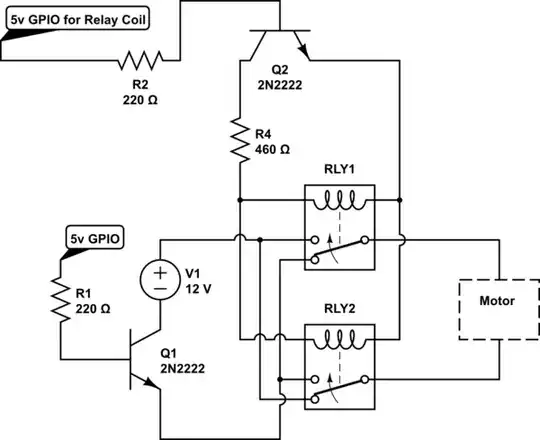
simulate this circuit – Schematic created using CircuitLab
I am trying to be able to switch off the motor, then energize or de-energize the relay coil for a motor direction change. I can't get this to work. I am just a very beginner and am trying to learn.
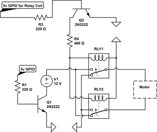
But if I delete the two lines and put a "GND" it works. Is GND not the negative terminal of the 12V battery? How can I get this to work? I would like to understand and also know what kind of diode or protection for my gpio pin would be suitable for this circuit.
Thanks