7

Page 29 of this DAC datasheet gives a typical operating circuit. I notice the power supplies have two decoupling capacitors in parallel: 100nF and 10μF.

What caught my eye is that there is a different symbol for each. (One has a curved edge, the other not.) As I understand, one is a "polarised" capacitor, and the other is not.

What is the qualitative difference between the two capacitors? Why are the types mixed in this application?

Randomblue
  • 10,953
  • 29
  • 105
  • 178

4 Answers4

13

These are decoupling capacitors. They are there primarily for two reasons:

  1. Power supplies take time to respond to a demand for more current from the device. The capacitors act as a local reserve until the power supply responds.
  2. Digital logic devices demand current very abruptly (due to the steep logic edges). The inductance of the power supply traces makes it impossible to transfer a step in current from a power supply to the logic chip. To solve the problem, one places "decoupling" capacitors very close to the chip. As the remaining traces are very short, the edge problem is reduced.

The reason for the two different types of capacitors is as follows:

  1. The device apparently requires a 10µF decoupling capacitor. Capacitors of this size are typically electrolytic capacitors. The problem is: they respond quite slowly compared to the edge time.
  2. To solve the problem, one places a (typically) ceramic capacitor in parallel. To simplify the issue: they only exist in fairly small values.

Functioning: The ceramic capacitor (100nF) smoothes the edge time of any current requests from the device and the electrolytic capacitor (10µF) supplies the bulk of the current once it kicks in.

Randomblue
  • 10,953
  • 29
  • 105
  • 178
ARF
  • 5,169
  • 9
  • 42
  • 69
  • @Randomblue If you are unfamiliar with decoupling search for "decoupling" and sort by votes. I remember that one of the questions with many (but not most) votes that comes up has a truly superb answer. – ARF Aug 11 '12 at 21:11
  • Are you thinking of [this answer](http://electronics.stackexchange.com/a/2274/5872)? – Randomblue Aug 11 '12 at 21:15
  • @Randomblue Sorry, I did not find it immediately when I wrote my last comment. I looked again and it was [this answer](http://electronics.stackexchange.com/a/15143/8534) I was thinking of. Very technical but maybe of interest to you if you are curious about the physical effects at play is also [this question](http://electronics.stackexchange.com/q/15369/8534). – ARF Aug 11 '12 at 21:32
  • 1
    And to complicate the issue again, you can get 10 uF ceramics in 0805 surface mount packages... – Chris Stratton Aug 11 '12 at 21:34
  • @ChrisStratton Very true and they could typically replace the entire combination of two capacitors. (Depending on ESR.) The problem is that they are far more expensive than the combination made from two capacitors. – ARF Aug 11 '12 at 21:37
  • @ArikRaffaelFunke Through hole electrolytics are cheap, but surface mount ones tend to be surprisingly expensive - the multilayer ceramics can actually be cheaper if you are doing prototype or limited run SMT. They also take up more space... but then are easier to find if you drop one. – Chris Stratton Aug 11 '12 at 21:44
  • @ChrisStratton Thanks for pointing this out. I appears the case is no longer as clear-cut as it was. I just checked at Radiospares and it would appear to come down to the voltage rating: Above 16V, 10µF SMT electrolytics are clearly cheaper. At about 16V, electrolytics are only slightly cheaper. Below 16V, multilayer ceramics are slightly cheaper. - Interesting... – ARF Aug 11 '12 at 22:01
  • @Randomblue The following [article by Maxim](http://www.maxim-ic.com/app-notes/index.mvp/id/5100) explains very well the need for decoupling capacitors of different sizes from a frequency viewpoint. Useful as a reference. See section "Selection of Decoupling or Bypass Capacitors". – ARF Aug 13 '12 at 00:05
6

In this answer different capacitor symbols are discussed. The asymmetrical one will be an electrolytic, which is polarized, and then the difference between the straight and the curved line allows you to identify the polarization.

Nevertheless the same symbol is also used for non-polarized capacitors, which is nonsense, because there the orientation doesn't matter, which should be indicated by a symmetrical symbol.
In that case an electrolytic is indicated by a plus next to the symbol:

enter image description here

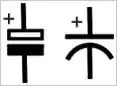
Here there's no plus, but the 100 nF uses a different symbol, so it's safe to assume that the ones with the curved lines are electrolytics. Yes, it's complicated.

nishu says the polarized (electrolytics) are mainly used for high voltage, but that's not completely true. Mains voltage EMI suppression capacitors are non-polarized, and have to be , because of their AC use. On the other hand, in this schematic a polarized cap is used for 5 V DC, so that isn't high voltage.

Electrolytics are mainly used for higher capacities, say starting at a few µF. You can have ceramics with that capacity too, but they're more expensive, and then most often aluminium electrolytics are chosen, despite their worse performance.

Conclusion: the 10 µF parts are electrolytics, preferably tantalum. The 100 nF are ceramics, preferably X7R.

stevenvh
  • 145,145
  • 21
  • 455
  • 667
1

The next page explains it under layout guidelines: The polarized capacitors are tantalum bead type and the non-polarized capacitors next to them should be low ESR and low ESL ceramic capacitors.

My main guess why both are used here is because smaller ceramic capacitors are better for filtering out high-frequency noise, while the tantalum capacitors can store larger amounts of energy. They can also have higher ESR and ESL than the smaller ceramics do, so they won't be able to respond as quickly as ceramics to high current demands. So ceramics respond faster and provide some extra time for the current to start flowing out of the tantalum capacitors.

AndrejaKo
  • 23,261
  • 25
  • 110
  • 186
-3

Polarized caps are typically used situations such as DC line filtering to reduce noise related to uneven voltage levels after rectification from an AC source.

Nishu
  • 446
  • 2
  • 6
  • 16