2

I'm thinking about the design of an AM receiver frontend that needs to select between three channels. The community suggested that I investigate manually wound loop antennas, and they seem like a nice choice.

AM loop antennas are designed for resonance at a tuned frequency within a range allowed by a variable cap. The loop is inductive, so at the tuned station the loop and the cap resonate.

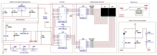
For my application, a cap with a wide range is not a good idea. I'd prefer to have three individually tunable sections that can retain their tuning, to be switched digitally. A circuit diagram follows (limited by my poor tablet software):

tuner

The sections are tunable around 3.33, 7.85 and 14.67 MHz, respectively. In each of the three tuning sections, the first cap is variable and the second one is fixed. The trim caps are 3-10, 4.5-20, and 8-45 pF, respectively. Once the trim caps are tuned they shouldn't have to change (much), barring aging components, mechanical antenna distortion, etc.

The switches are digitally controlled RF switches. An SP3T switch or individual switches are possible.

Is this a reasonable approach? For the RF switches can I use a topology similar to a digital pass gate with parallel NPN and PNP RF transistors?

Reinderien
  • 3,102
  • 16
  • 28

3 Answers3

5

If you follow the cap switching topology, a PIN diode suitable for use at your frequency of interest (i.e. MAcom MA4PH301) would be less complex than the transistor switch you mentioned in your question. In the sketch, L1 & C1 form the resonant tank circuit. R1 is chosen to limit the forward bias current from your control voltage to a value within the limit of your chosen PIN diode. The PIN diode is acting as a switch, not a variable capacitance device (varactor).

schematic

simulate this circuit – Schematic created using CircuitLab

AlmostDone
  • 1,749
  • 7
  • 11
  • The RF choke is unnecessary, the varactor is reverse biased and only passes leakage current so the value of R1 will be very high ...perhaps 100k or so to prevent loading the varactor capacitance. . – Jack Creasey May 20 '18 at 23:25
  • 1
    This suggestion uses a forward biased PIN diode, not a varactor. If a high enough value for R1 can be used, then the RFC can be eliminated. – AlmostDone May 20 '18 at 23:46
  • You are right ...you did specify a PIN diode which is totally inappropriate for a tuning application: http://www.skyworksinc.com/uploads/documents/Design_With_PIN_Diodes_200312D.pdf The capacitance range for PIN diodes is far to small for anything less than microwave use. – Jack Creasey May 21 '18 at 02:09
  • 2
    @JackCreasey I agree, they wouldn't be useful for modifying the capacitance of a capacitor. But they work well as switches as in the topology described in OP's question. Replace the switch contact with the PIN diode to accomplish the same result. Many are made for microwave use, but they are available for HF use as well. This particular one has f-min of 1MHz which is within the range of OP's interest. http://www.richardsonrfpd.com/pages/Product-Details.aspx?productId=22045 – AlmostDone May 21 '18 at 02:33
2

AM loop antennas are designed for resonance at a tuned frequency within a range allowed by a variable cap. The loop is inductive, so at the tuned station the loop and the cap resonate.

Regular loop antennas i.e. ferrite rod antennas can be tuned but the tuning is quite broad because they don't have a high Q factor. This means that no-matter how good your capacitor tuning is you might still receive several stations simultaneously and not be able to distinguish between them.

If you re-wound the coil to give a higher Q you could get a lot better selectivity when tuning but, then you hit the next problem - the overall Q of the tuned circuit will be different at one end of the tuning band compared to the other end. I'm not saying it's a showstopper but you should be aware that what might work at one end of the band may not produce the desired results at the other end of the band.

This could be mitigated by also having a different value resistor in parallel with the switched tuning capacitor.

Andy aka
  • 434,556
  • 28
  • 351
  • 777
  • The antenna I am looking at now is air core and not ferrite. See https://aa7ee.wordpress.com/2013/11/17/a-tuned-loop-antenna-for-the-am-broadcast-band/ for example. – Reinderien May 21 '18 at 10:13
  • I think it's okay for the antenna to be non-selective, because I intend to add a selector filter between the antenna and the LNA. – Reinderien May 21 '18 at 10:14
  • @Reinderien I'm confused - your question appears to be all about tuning the antenna with capacitors so have you decided that you don't need to use it in a tuned circuit anymore? You cannot talk about the selectivity of the loop antenna without considering that a tuning capacitor is involved. – Andy aka May 21 '18 at 10:25
  • To clarify - I would like the antenna to be tuned, but it's okay if its Q is not wonderful, because I'd then improve it with an additional passive network. – Reinderien May 21 '18 at 10:28
1

If you want to achieve digitally tuned stations I'd suggest you would be better to use tuning diodes (varactor diodes) and a single tuning inductor.

NXP are my favorite supplier, and they make diodes up to 120 pF or so ….for example the BB201 which can provide a decade of adjustment (10-100 pF) with only 20 V drive.

To sum up the comments: It's your choice ….I simply made the suggestion that tuning diodes could work for you. It's up to you to decide if that does work, and which device is best. The BB201 is the only device I have used, hence suggesting it as an example. The BB171 does 17:1 ...that would seem not to yet fit your 19:1 requirement. Notice however that the minimum reverse bias is always at some level 0.5 or 1 V, so there is room to play at the low voltage end.

There are other devices that meet your requirements, you could have easily looked them up yourself.
Of the several I looked at the Infineon BB640 among the highest lo/hi ratio at 19.5-25:1, but again it's up to you to decide what fits your need.

Jack Creasey
  • 21,428
  • 2
  • 15
  • 29
  • Quite interesting. Why an additional tuning inductor if the antenna is already inductive? – Reinderien May 21 '18 at 07:22
  • If the antenna is a sufficiently high Q inductor of a suitable value, you can use it as the tuning inductor. If it's low Q, a separate inductor will allow sharper tuning. Where is your selectivity? (is this a superhet RX?) –  May 21 '18 at 10:02
  • My intent is for near-zero-IF heterodyne, i.e. downmix to about 50kHz, but that is not solid yet. For selectivity - these are special allocation government timekeeping bands with what appears to be generous guard space. The signal bandwidth itself is less than 5kHz, but the total channel bandwidth is between 170 and 700 kHz depending on the channel. – Reinderien May 21 '18 at 10:11
  • I've also noticed that a decade range is not sufficient. (14.67/3.33)^2 = 19.4 minimum ratio. – Reinderien May 21 '18 at 18:40
  • @Reinderien The tuning diodes are easily stackable (paralleled) to suit any need. The 10:1 ratio is of course the most linear range of the diode. Since you are using digital control this can be extended to some extent. – Jack Creasey May 21 '18 at 19:34
  • Ok, but... If you put two in parallel and you double both the minimum and maximum capacitance, is there any net benefit? – Reinderien May 21 '18 at 19:35
  • There is if you are willing to go outside the linear operation area (higher revers voltage). For the BB201 you should be able to get at least 12:1 ratio. But of course there are limitations. – Jack Creasey May 21 '18 at 19:44
  • But going outside of the linear area could simply be done with one diode. Also the BB171 seems to have a better range. – Reinderien May 21 '18 at 19:48