I'm trying to repair the generator board on a Sonix IV ultrasound cleaner. I need to find a replacement for a transistor (in a TO-3 package), but the manufacturer uses an in-house part id, so I'm trying to figure out what kind of transistor this is.
This guy has a similar problem, but a slightly different generator board: Replacing a transistor when I can't find any info on it. I suspect it is the same transistor though. Like him, the manufacturer is unwilling to give information about the part.
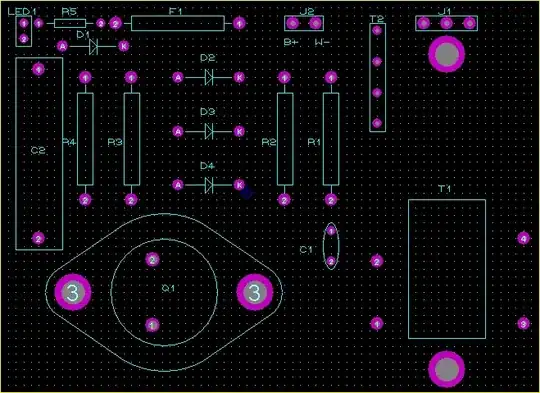
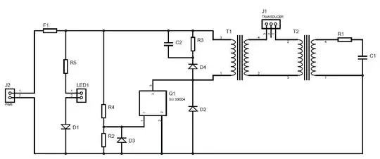
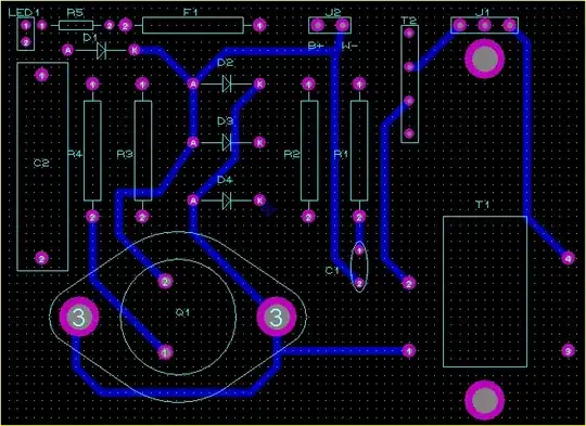
I have tracked the part-placement and wiring on the board, and created a schematic. Can anybody use this to suggest a suitable replacement part?
Schematic:
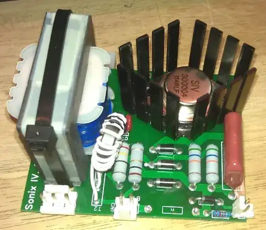
Board:
Top layer PCB:
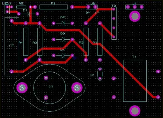
Bottom layer PCB:
Silkscreen: