3

When we develop a new product we need to pass the EMC test. I really wonder what the current path during a electrostatic discharge test is.

Here is the test situation:

  1. If the EUT (equipment under test) is a metal shell, is there a discharge path? If yes, what's the path going to? The ground?

  2. If the EUT is not a metal shield (for example a plastic shell,) does a path exist? What's the discharge path?


Let's assume the EUT is a battery powered plastic shell device which has a PCB inside. When we do the electrostatic discharge test at a voltage of +-6.6kV, the discharge current has an influence on the device such that it causes it to work abnormal. So what's the discharge current path?

enter image description here enter image description here


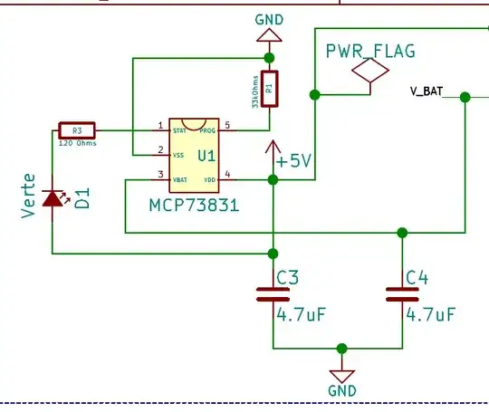
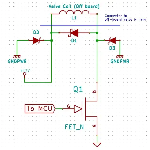
[updated] I added a new picture to assume the discharge current loop, that is my confusion.

Can I always find the discharging current loop in my test?

Q1 is easy to consider as the discharging current flows through the metal shell, but in the situation of Q2 I cannot find a current path.
enter image description here

JRE
  • 67,678
  • 8
  • 104
  • 179
lukeluck
  • 157
  • 1
  • 2
  • 8

2 Answers2

2

If there are power cords, then the ESD discharge may use the 117VAC power lines.

If the DUT is floating atop insulation, then the Displacement Current is the path.

analogsystemsrf
  • 33,703
  • 2
  • 18
  • 46
  • Excuse me,what do you mean by "the Displacement Current is the path" – lukeluck May 15 '18 at 02:55
  • 1
    @lukeluck I think the sentence is pretty clear. The path for the current is *displacement current*; you won't get far on this topic without basic understanding of solid state electronics and Maxwell... – Marcus Müller May 15 '18 at 07:18
  • displacement current is a definition?can you draw me a picture like figure3? – lukeluck May 15 '18 at 10:13
  • 2
    Use wikipedia. One example of displacement current is how current flows through a capacitor while no electrons jump from one plate to the other. – bobflux Mar 13 '21 at 11:24
0

The EUT will have a reactive path that must withstand the dielectric breakdown of the applied discharge electric field. It may also have a 0V conductive shield or an EMI spray ground that shields the impulse E field from inerference.

Damage or false operation may occur from ground shift, inductive signal induction, conducted signal or capacitive or inductive coupling to signals.

This way you do not have to feel the current spike.

Even portable testers have a proper ground connection, so there is an inductive current loop, but the good testers are low inductance which can raise the spectrum of the discharge noise.

enter image description here

Tony Stewart EE75
  • 1
  • 3
  • 54
  • 182
  • 真的吗 ? This tester is the best Swiss brand – Tony Stewart EE75 May 15 '18 at 03:53
  • As we know,there must be a loop so that the current can flow,in my Q1 I think the current loop is that the charge flow to ground throw metal shell,is this thought correct? And in my Q2,obviously there there does not exist such a loop,if there is no loop then how the current flow?(but in reality I really see the discharge spark during my battery powered EMC test).I can't understand how the charge transfer? – lukeluck May 15 '18 at 03:54