2

I would like to create a PWM generator with a 555 timer (like suggested here), but I would like to be able to adjust the duty cycle with a microcontroller. I would simply use PWM from the microcontroller, but I need a high frequency as I am driving motors and they produce a tone with the frequency of the PWM. This happens to be audible when using PWM from the microcontroller. (The frequency is only 490Hz)

Please note that this signal will not directly drive the motor, as it will be fed into a controller which drives the motor.

What would be the best way to accomplish this?
John Leuenhagen
  • 436
  • 6
  • 14
  • Are you driving the motor directly off the PWM? Do be aware that you'll need a buffer and a flyback diode or you risk destroying your 555. – Hearth May 12 '18 at 20:21
  • @Felthry sorry, I forgot to mention that this PWM will be fed into a controller, so that shouldn't be a problem. I'll update the question. – John Leuenhagen May 12 '18 at 20:24
  • 4
    Why can't you generate a faster PWM on your microcontroller? – jonk May 12 '18 at 20:26
  • @jonk I am not directly programming the microcontroller, as I am using [Johnny-Five](http://johnny-five.io/) to control it from a Raspberry Pi. Unfortunately the firmware being used on the AVR (Firmata) doesn't support high frequency PWM. – John Leuenhagen May 12 '18 at 20:29
  • @jonk 490Hz is approximately the frequency of the built-in pwm on the Arduino board. – Hearth May 12 '18 at 20:29
  • @Felthry I'm sure an Arduino is capable of higher frequency PWM. Don't they use ATmega AVR devices? Those things can do a LOT faster, memory serving. – jonk May 12 '18 at 20:33
  • 1
    @jonk 490Hz is what you get when you use the analogWrite() function on an unmodified Arduino. – Hearth May 12 '18 at 20:34
  • 4
    @Felthry So it's just a library code problem? Don't use the library. Write some *actual* code. – jonk May 12 '18 at 20:34
  • @jonk please look at my previous comment. – John Leuenhagen May 12 '18 at 20:37
  • 1
    @JohnLeuenhagen I'm confused. Looks like Johnny-Five *runs* on an RPi. Is there a 2nd micro system here? Or just the one? ... Better yet, why don't you DIAGRAM what you have. Bits and pieces are coming out in comments that should be clearly laid out in the question. – jonk May 12 '18 at 20:37
  • @jonk The RPi is connected via serial to the microcontroller ( USB in the case of Arduino), and the RPi can send serial messages to the AVR to do whatever you might program an AVR to do. – John Leuenhagen May 12 '18 at 20:40
  • Welcome to EE.SE! Keep in mind that questions about optimization require a definition about what problem dimensions are to be optimized for your application, such as size, speed, energy consumption, user experience, etc. Since these can't be optimized all at once, you need to have a good idea of which ones are most important to you, and be able to articulate that clearly to us. – Dave Tweed May 12 '18 at 21:00
  • @JohnLeuenhagen So, weeding through all these tiny bits and pieces you leak out slowly over time, I gather that the AVR is running Johnny-Five and drives the motor controller and you send messages to the AVR from an RPi. Am I wrong? – jonk May 12 '18 at 21:00
  • 1
    @jonk: I got the impression that "Johnny Five" is running on the RPi, and that something called "Firmata" is running on the Arduino. But I could be wrong, and I agree, this is "death by a thousand cuts" in terms of getting information out of the OP. – Dave Tweed May 12 '18 at 21:02
  • 3
    @DaveTweed I think you worked it out better than I did. I think the OP would be served better by deepening their knowledge of what they already have in place than by adding yet another electronic module (555) to a growing heap of them. One can stay shallow, I suppose, and just add one colostomy bag after another to get a job done. But it's not interesting to me, then. Oh, well. – jonk May 12 '18 at 21:14

2 Answers2

2

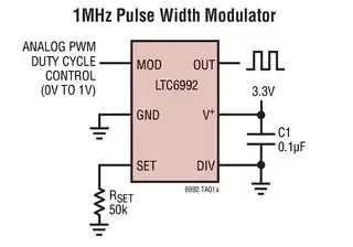
Linear's LTC6992 might be what you want.

enter image description here

Figure 1. The LTC6992 gives a PWM output at a set frequency up to 1 MHz for an analog input signal of 0 to 1 V.

You could then use your low frequency PWM and low-pass filter to generate an analog voltage, scale this down to 0 to 1 V and generate your high-frequency PWM with the LTC6992.

There will be a response time penalty with this approach and this can be calculated based on the RC time-constant of your filter.

Transistor
  • 168,990
  • 12
  • 186
  • 385
0

"Best" is a somewhat flexible concept. Assuming you have access to some kind of serial bus, I would think about a dual-channel digital potentiometer. Maybe something like this: http://www.analog.com/en/products/digital-to-analog-converters/digital-potentiometers/ad5122.html

And do an out-right replacement of the resistors in the traditional 555 astable configuration.

pgvoorhees
  • 2,496
  • 16
  • 14