7

I am building an Wooly Mammoth audio circuit, and I am really interested in finding how and why it works. You can check out and simulate the whole thing here. I must say I haven't been able to get any valuable result from simulation.

It provides a fuzz distortion effect. In fact, it's based in the well-known Fuzz Face. You may notice Q1's collector and Q2's base common node, as well as the feedback net that connects Q1's base and Q2's emitter. In the article I link to, RG Keen makes an extensive analysis and calls that configuration voltage feedback biasing. Unfortunately, I haven't been able to trace any other data about this.

I have isolated the DC circuit for you:

Wooly Mammoth Bias circuit

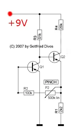
When trying to solve it, I get stuck at proposing and checking hypothesis: I don't really know whether one or both transistors are in saturation region. I assume that, being this kind of effect, at least one of them is. But I find no way to prove it.

One of the Mammoth's addition to the Fuzz face circuit is the Pinch potentiometer. It seems to change the bias point, while users say it works as some sort of noise gate. I have not been able to see that by simulating.

So I would take a good piece of advice on how to solve the DC circuit (is there a possible analytical approach?) to understand the principles of that bias configuration. Also, I would appreciate some help regarding simulation, as I'm sure there must be something useful to get.

Thank you very much.

Serge
  • 577
  • 1
  • 3
  • 14
  • It's impossible to analyze this circuit without knowing what is the input and what is the output. – Olin Lathrop Aug 06 '12 at 21:36
  • 2
    @OlinLathrop And I prefer my circuits time-independent and linear. – Kortuk Aug 06 '12 at 21:53
  • @OlinLathrop Thank you for your comment. How specifically should be input and output defined? I think all we can assume at first is that the input signal is *clean* sound coming from the guitar pickup: band limited (way below 20KHz) with a nominal level of about -20dBU (0.0775V RMS). The output should be a distorted signal that may approximate to a square waveform. I'm afraid I've got no images, but it can be heard in their [official website](http://media1.zvex.com/FLASH/MAMMOTH/). – Serge Aug 06 '12 at 21:58
  • 1
    I believe that @OlinLathrop is talking about the fact that the input and output of the circuit are not labeled. The schematic shown is a crop from the very first link in the post. Serge's question is specifically on the DC biasing of the circuit, and so he has cropped off all portions of the circuit that are capacitively coupled. – W5VO Aug 06 '12 at 22:29
  • Yes, we still don't know what node of this circuit is being driven and by what impedance, and which node you expect to get the output signal from. – Olin Lathrop Aug 06 '12 at 23:11
  • 2
    @OlinLathrop right - but that's OK because the inputs and outputs are AC coupled into the circuit shown, and the question is about solving the circuit at DC. Didn't you ask for users to [crop their images to only the relevant details](http://meta.electronics.stackexchange.com/a/1391/638)? – W5VO Aug 07 '12 at 03:13
  • @w5vo: First, without seeing that the inputs and outputs are capacitively coupled we don't know that they aren't relevant to the DC bias. The OP said he "isolated the DC circuit", but OPs say a lot of stuff and I don't know that he knows how to do that correctly. *You* are the only one who actually said the rest is capacitively coupled. Second, he is also asking about the fuzz effect where injection point and take out point certainly matter. Even if not, the biasing makes more sense in light of intended AC operation. – Olin Lathrop Aug 07 '12 at 11:19

1 Answers1

4

The DC analysis isn't that difficult.

EDIT: I see a far simpler analysis:

\$I_{B1} = \dfrac{V_{C1} - V_{BE2} - V_{BE1}}{R_2 + P_2}\$

\$V_{C1} = 9V - I_{C1} \cdot R_3 = 9V - \beta I_{B1} \cdot R_3\$

\$ \rightarrow I_{B1} = \dfrac{9V - V_{BE2} - V_{BE1}}{R_2 + P_2 + \beta R_3}\$

Now:

\$I_{E2} \approx \dfrac{V_{C1} - V_{BE2}}{R1}\$

\$V_{C2} = 9V - I_{C2} \cdot R_4 \$

Assume a value for the base-emitter voltages and P2 ,solve for the collector currents and check for active/saturation operation.

Alfred Centauri
  • 26,502
  • 1
  • 25
  • 63