0

I need to create a simple power supply circuit to feed 10 external boards, similar to a USB power hub.

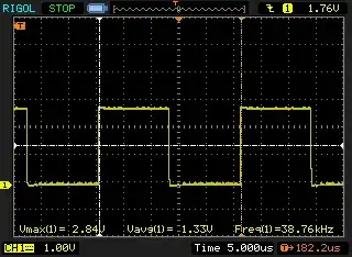
My power source is an AC to DC adapter measured to output 5V 10A. I need to limit the maximum amount per output to 1A. The external boards (U1, U2, etc) are audio boards, they have an MCU, an audio player, 5W amp and speakers. Each board uses from 300mA to 700mA (they vary due to music/frequencies), so 1A max should be enough.

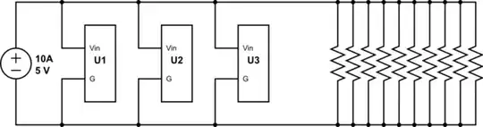
I'm a beginner who understands a voltage divider quite well, but that is the first time I have to apply a current divider. I had a look at some tutorials/books, the math seems simple in my context, but it's still not clear to me what resistor values I should use and if I'm connecting the outputs correctly (I'm not used to do things in parallel). Below is how I think it should be:

schematic

simulate this circuit – Schematic created using CircuitLab

About the resistance, if I use the general formula IBRANCH = IS(RTOTAL/RBRANCH) I will get 1A for any kind of resistance as long all values are the same (for example, they could all be 100ohms or 1K)..So what value is best for this application?

Chu
  • 361
  • 4
  • 15
  • It feels weird to upvote this question, because your suggested solution is very far from how a current limiter should be constructed. Do you use a voltage divider to _limit_ the voltage? But it's still a good question. A solution is more advanced than this, though. – pipe May 07 '18 at 13:30
  • Is it a 10 A current source with 5 V maximum compliance voltage? Or is it a 5 V voltage source with 10 A maximum output current? – The Photon May 07 '18 at 17:07

3 Answers3

4

The current of the voltage source will automatically be divided between each board as needed. No need to get fancy.

You can just connect all those board in parallel. In fact that's what your schematic actually does. You just added 10 resistors that will do nothing but waste power, remove those.

I would suggest adding a filter/reservoir capacitor between ground and Vin on each board as close as possible to that board. This will reduce noise that can affect the output and the spikes in voltage when a board suddenly needs to draw more current.

Tony Stewart EE75
  • 1
  • 3
  • 54
  • 182
ratchet freak
  • 2,803
  • 14
  • 12
  • I see...that's why I was worried, noise and spikes from one board could affect other boards and I need them all to be stable. I will do this then, just connect all boards in parallel and add caps between the power terminals if limiting current is too complicate. Thanks! – Chu May 07 '18 at 13:49
  • How do you think current is shared in a PC with 500W? If the Load regulation is good, or the ratio of surge load to source impedance, then the ripple is the same. The source mipedance is not Vout/Iout but depends on error gain. then the audio amps should have good PSRR – Tony Stewart EE75 May 07 '18 at 16:34
1

this is not an answer .... i could not draw a schematic in a comment

this is your schematic that has been drawn more clearly

as you can see, the resistors do not distribute the current between the boards

schematic

simulate this circuit – Schematic created using CircuitLab

jsotola
  • 2,497
  • 2
  • 12
  • 21
0

Resistors are not what you want. Depending on the purpose of limiting the current there are possible solutions.

Maybe you want resettable fuses (PTC) if circuit protection is your aim.

LDO regulators are another method, with faster and sharper limiting.

Whatever method you use will cost a bit of voltage, in other words you might have to feed in 5.1V to get 5.0V out.

Spehro Pefhany
  • 376,485
  • 21
  • 320
  • 842