5

For a project I am working on, I want to build a 9x9 monocolor LED matrix also with 9 push buttons to control the LEDs using the PIC. So far I have gathered that I think I will be needing shift registers to drive the cathodes and shift-register chips to drive discrete transistors for the anodes. I will also require shift registers for the push button inputs as well.(Please correct me if i'm wrong).

I am having trouble looking for relevant information online (e.g. what components to choose), can anyone give me some ideas to research or any relevant advice would be most helpful! Thanks

Daniel
  • 53
  • 5

1 Answers1

5

I'll assume that you want to drive the matrix common anode, i.e. one anode line at a time.

You already mentioned the transistors for the anodes, and that's right, you'll need them because you'll have to supply current for up to 9 LEDs at a time, and that's too much for a logic IC like a 74HC595 shift register. That will be 9 PNP transistors.
But you'll also need transistors for the cathodes; you want to drive up to 9 outputs low simultaneously, and at 20 mA per LED (a typical value) that's too much for a 74HC595. That's 9 NPN transistors.

You have to control 18 lines, so you can use three 74HC595s for that, where you shift in 18 bits for each scan row: 9 bits to select the anode line, that's 1 bit low, the rest high, and 9 bits for the cathodes, high for on, low for off.

The good news is that you don't need a separate shift register for the buttons: connect each of them to an anode line, with the other pins tied together to an input, and connect a pull-down resistor on that input.
Now, every time you scan one anode line you can see on the input if the button for that line is pressed; input high = pressed, input low = released.
If you expect users will press two buttons at a time (they always will!) you'll have to put diodes in series with the buttons to prevent that other rows of LEDs than the selected one light up.

edit re your comment
In your sketch you have the LEDs' resistors in the columns, which is OK if you drive the display one row at a time. Otherwise the resistor will share the current for all LEDs in a row, and the brightness will vary with the number of LEDs which are on. In my schematic below I moved them to the rows, so that each LED has its own resistor.

enter image description here

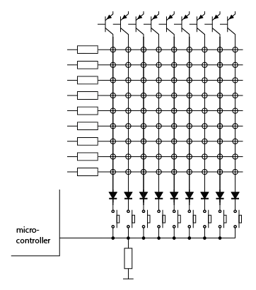
The circles represent the LEDs. The microcontroller input will be pulled low by the resistor. If one of the buttons is pressed the input will go high when the associated column is selected. So upon each column scan you can check the status of one button. The diodes prevent lighting of LEDs in other columns than the active one if more than one button is pressed simultaneously.

stevenvh
  • 145,145
  • 21
  • 455
  • 667
  • A shot in the dark, but can you still help me (not sure if you will receive this reply). – Daniel Sep 29 '12 at 12:40
  • 1
    @Daniel - Yes, I can hear you (a user always gets notified of comments to his posts). Let me know if my answer needs clarification. – stevenvh Sep 29 '12 at 12:46
  • Ah, was I hoping this would be the case. Thus far I have built a somewhat working LED matrix. I haven't really started the programming part, but I am able to light up LEDs within the matrix.EDIT: sorry, new to this site. I accidentally pressed enter, I haven't finished writing – Daniel Sep 29 '12 at 13:09
  • I'm not sure how I would connect the buttons, could you please clarify that point for me? What I was thinking was to connect each push button to one msp430 I/O pin, but it seems that there are only eight, and I need 9 buttons. – Daniel Sep 29 '12 at 13:15
  • [here](http://i.imgur.com/3tOp1.jpg) is a poorly drawn sketch of the circuit. Each base resistor is connected to one of three 74HC595 and the 595s are connect to the msp430. Thanks – Daniel Sep 29 '12 at 13:26
  • 1
    @Daniel - updated my answer. Hope it's more clear now, but questions are still welcome. – stevenvh Sep 29 '12 at 14:50
  • I see, it makes sense! I will get back to you if I have any more questions. Thanks – Daniel Sep 30 '12 at 01:20
  • Hi Steven, are you familiar with msp430 programming? – Daniel Oct 10 '12 at 10:58
  • @Daniel - only limited: I've used the MSP430F1101 once, but that only has 1 kB of memory, so you can imagine that wasn't much code :-) – stevenvh Oct 10 '12 at 11:12