The simplest extension of your thoughts would be the following schematic:
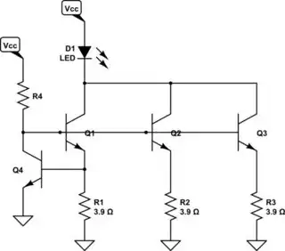
simulate this circuit – Schematic created using CircuitLab
This doesn't include separate current monitoring for each of the current-sharing BJTs, \$Q_1\$-\$Q_3\$, but given that their bases are two \$V_\text{BE}\$'s above ground there should be a roughly approximate sharing of currents. \$V_\text{BE}\$ variation between BJTs will have the largest impact on the sharing, but \$\beta\$ variation won't matter too much on that score. \$\beta\$ variation will matter more in sizing \$R_4\$.
Keep in mind that there will be differences in temperature and that this will lead to still further shifts (in a bad way) in terms of the sharing. So if you can help by putting them in thermal proximity to each other, it may help a little bit. Also, keep \$Q_4\$ thermally isolated, if possible. It shouldn't need to heat up above ambient that much and the better isolated it is from the other BJTs, the better its regulation of the total current.
The current sharing, ignoring thermal variation for now, is based upon the following:
$$\begin{align*}
I_{\text{E}_1} \approx I_{\text{C}_1} &= I_{\text{S}_1}\cdot\left(e^\frac{V_B-I_{\text{E}_1}}{V_\text{T}}-1\right)\\\\
I_{\text{E}_2} \approx I_{\text{C}_2} &= I_{\text{S}_2}\cdot\left(e^\frac{V_B-I_{\text{E}_2}}{V_\text{T}}-1\right)\\
&.\\
&.\\
&.\\
I_{\text{E}_N} \approx I_{\text{C}_N} &= I_{\text{S}_N}\cdot\left(e^\frac{V_B-I_{\text{E}_N}}{V_\text{T}}-1\right)
\end{align*}$$
Ignoring the base current of \$Q_4\$ to simplify the problem slightly, we also know:
$$\begin{align*}
V_{\text{E}_1} = R_1\cdot I_{\text{E}_1} &\approx R_1\cdot I_{\text{S}_1}\cdot\left(e^\frac{V_B-V_{\text{E}_1}}{V_\text{T}}-1\right)\\\\
V_{\text{E}_2} = R_2\cdot I_{\text{E}_2} &\approx R_2\cdot I_{\text{S}_2}\cdot\left(e^\frac{V_B-V_{\text{E}_2}}{V_\text{T}}-1\right)\\
&.\\
&.\\
&.\\
V_{\text{E}_N} = R_N\cdot V_{\text{E}_N} &\approx R_N\cdot I_{\text{S}_N}\cdot\left(e^\frac{V_B-V_{\text{E}_N}}{V_\text{T}}-1\right)
\end{align*}$$
Therefore,
$$\begin{align*}
V_{\text{E}_1} &\approx V_\text{T}\cdot\operatorname{LambertW}\left(\frac{R_1\cdot I_{\text{S}_1}}{V_\text{T}}\cdot e^\frac{V_B}{V_\text{T}}\right)\\\\
V_{\text{E}_2} &\approx V_\text{T}\cdot\operatorname{LambertW}\left(\frac{R_2\cdot I_{\text{S}_2}}{V_\text{T}}\cdot e^\frac{V_B}{V_\text{T}}\right)\\
&.\\
&.\\
&.\\
V_{\text{E}_N} &\approx V_\text{T}\cdot\operatorname{LambertW}\left(\frac{R_N\cdot I_{\text{S}_N}}{V_\text{T}}\cdot e^\frac{V_B}{V_\text{T}}\right)
\end{align*}$$
Any particular ratio of currents is then:
$$\frac{I_{\text{C}_i}}{I_{\text{C}_j}}=\frac{\operatorname{LambertW}\left(\frac{R_i\cdot I_{\text{S}_i}}{V_\text{T}}\cdot e^\frac{V_B}{V_\text{T}}\right)}{\operatorname{LambertW}\left(\frac{R_j\cdot I_{\text{S}_j}}{V_\text{T}}\cdot e^\frac{V_B}{V_\text{T}}\right)}$$
(Obviously, you will probably want \$R=R_1=R_2=...=R_N\$.)
Variation of \$I_\text{S}\$ for BJTs in the same family might account for a band of about \$30\:\text{mV}\$ in their \$V_\text{BE}\$. If you can keep the thermal variations to within a band of about \$15\:^\circ\text{C}\$, then this would be about another \$30\:\text{mV}\$ of variation in their \$V_\text{BE}\$. So call this a total worst case situation (all things aligning wrongly) of perhaps a band of about \$60\:\text{mV}\$.
Given that the voltage drop across \$R=R_1=R_2=...=R_N\$ is at least 10 times that much and probably still more, the current sharing should remain pretty good (\$\pm 30\:\text{mV}\$ variations vs \$700\:\text{mV}\$ for the base voltage of \$Q_4\$.) Perhaps \$10\$% span of variation in the voltages over each emitter resistor and so the sharing should be close enough to be useful.
So this technique can work, I think. (Not that I've done it for this circumstance.) You could eliminate the thermal variation by adding more BJTs (Sziklai, for example) and therefore more tightly control the sharing. But I don't see a good reason to go that extra mile in the case you pose. So this should be fine.
The remaining problem will be setting the value of \$R_4\$. Clearly, there is also wide \$\beta\$ variation in BJTs and this also depends highly on temperature as well as collector current. So you will need to examine the datasheet to determine the worst case (smallest) value for \$\beta\$ that you expect and make sure that \$R_4\$ can provide at least that much base current to \$N\$ BJTs. You will also need some minimum collector current for \$Q_4\$.
Note that if the \$\beta\$ values are much better than expected, \$Q_4\$ will have to take up the slack in its own collector current. This will impact its \$V_\text{BE}\$ and therefore also the current setting. However, a 10-fold increase in \$Q_4\$'s collector current due to a prediction error caused by assuming worst-case \$\beta\$ values would only mean about \$60\:\text{mV}\$ variation in \$V_\text{BE}\$. It's unlikely that your prediction vs actual will be that bad. But you will have to determine how acceptable this might be.