0

I'm looking at the following datasheet for an accurate TCXO: TG2016SBN

It gives values for Rload and Cload, and AC coupling cap - which I've incorporated into a clock pulsing circuit. Will a simple comparator (with a bit of hysteris) be enough to clean this signal up for a CMOS clock input?

I've currently got the following circuit sketched up. The 20Ks should will give a paralel (small signal) load of 10K, and bias it at 1.65V DC coupled. I don't see anything wrong with it - the comparator is fast enough and in theory work.

enter image description here

The comparator is the following: LT6752

Cheers
Wes
  • 51
  • 3

2 Answers2

1

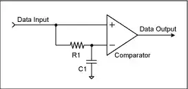
To avoid non 50:50 duty cycles on the output of the (excellent) comparator you have picked, I would directly feed one input from the TXCO and use a 10 k resistor feeding the other input with that "other" input being connected to a 10 nF capacitor to ground. Same story as a data slicer: -

enter image description here

This ensures your DC levels are set the same and the tolerance of all those 20 k resistors is not a factor any more.

Andy aka
  • 434,556
  • 28
  • 351
  • 777
  • Hmm, non 50:50 duty cycles aren't really a problem in my application, just counting those edges. I'll take look at the impedances that the crystal is seeing as they seem to be pretty strictly specced out. Cheers – Wes Apr 27 '18 at 17:15
0

I've had to interface 0.8V p-p clipped TCXO to CMOS several times. I've always found a 1nF AC coupling cap, and resistive biasing using a divider around the 200K level works fine.

For instance in this case for using a TXCO to replace the main RPi crystal.

https://raspberrypi.stackexchange.com/questions/74482/switch-out-the-x1-oscillator-on-a-rpi-2-3

colintd
  • 2,018
  • 2
  • 17