-1

I have a 74hc32 that feeds back the output from an or gate into its input. The independent input comes from a comparator that outputs high when the photoresistor voltage is greater than the referenced voltage divider. I'm trying to have the LED stay on forever after the comparator outputs high.

The issue I'm having is that the op amp is outputting 1.8 volts whenever the above condition is false, but it is still causing the logic gate to go high and turning on the transistor and led. I replaced the op amp input to the 74hc32 with a potentiometer and got to 3.2v before it triggered HIGH, so i don't know what the issue is.

I thought of two casuses:

  1. The 1.8v is above the datasheet max threshold for LOW on the 74hc32 but less than the minimum for HIGH, and something about the undetermined state is causing it to go high
  2. the 74hc32 turns on before the op amp, so it is reading an undetermined output before the op amp has a chance to output low.

I would like to know if there is a possible fix to this, if I did something wrong, and if I am misunderstanding something about my circuit. Thanks.
enter image description here

Kuramine
  • 13
  • 2
  • Are you using a potentiometer to set the supply voltage of the 74HC32? – Samuel Apr 24 '18 at 17:37
  • Yes because the datasheet says max vcc is 7v – Kuramine Apr 24 '18 at 17:39
  • The op-amp is type........? – Andy aka Apr 24 '18 at 17:46
  • 1
    Why do you have 4A and 4B attached to the battery directly, but Vcc connected through a resistor divider? That's not likely to work well. – The Photon Apr 24 '18 at 17:47
  • op amp is 741 tied every unused input to gnd and it didn't change the function – Kuramine Apr 24 '18 at 17:49
  • 1
    Please read [Rules and guidelines for drawing good schematics](https://electronics.stackexchange.com/q/28251/6334). Then re-draw your schematic according to those rules. You'll make it a lot easier for us to understand your problem, and maybe even make it easier for you to answer it for yourself. – The Photon Apr 24 '18 at 17:50
  • 1Y connected to the transistor base with no current limiting resistor is also likely to cause problems. – The Photon Apr 24 '18 at 17:50
  • Use a rail to rail opamp, not a 741. If you must stick with 1970s parts, even an LM358 will do at a pinch. –  Apr 24 '18 at 18:04
  • The new schematic is better but still hard to read. Put ground near the bottom of the page. Put power near the top. Make signals flow left to right. Indicate OR gates as OR gates, not random pins sticking out of a rectangle. – The Photon Apr 24 '18 at 18:06
  • Also, you've changed the actual circuit connections. Have you tested the new design on the bench? – The Photon Apr 24 '18 at 18:09

3 Answers3

1

This circuit can't work!
You feed the output of the OR-gate to it's input. (1B=1Y) Thus once it is high it can never go low again.

Let me elaborate: You don't have a stable reset state. Any glitch on start-up will get it stuck high. It might work now and then. Get yourself a register with a reset input and a clock:

schematic

simulate this circuit – Schematic created using CircuitLab

For your OP-AMP: you should make it into a Schmitt trigger by adding a resistor from the output to the + input. Look on the WWW how to do that and how to give it some hysteresis. It will shoot through the "dead zone" and your voltage problems are likely to be solved.

If you select a low voltage rail-to-rail op-amp the whole thing should be able to work anywhere between 3 and 9 Volts.

Oldfart
  • 14,212
  • 2
  • 15
  • 41
  • I should have clarified that that is exactly what I am trying to accomplish. that once the photoresistor voltage exceeds the reference, the led should stay on forever. – Kuramine Apr 24 '18 at 17:43
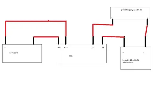
  • I'm trying to use a time delay relay like this one: https://imgur.com/a/nANAgGf Would it be better to short the independent input or the feedback input of the logic gate to ground during the delay? – Kuramine Apr 26 '18 at 15:16
0

I'm not even going to try to read that awful schematic- but it sounds like you need a way to reset the latch.

For example, put a series resistor (maybe 10K) between the output and feedback input and short the input to ground with a pushbutton switch. You can parallel the switch with a capacitor if you want to slow the latching action.

Spehro Pefhany
  • 376,485
  • 21
  • 320
  • 842
0

You have numerous problems.

  • 741 op-amps typically require 20 V difference between Vcc and Vee, but you've only supplied 6 V.

  • HC32 inputs 4A and 4B are tied to the 6 V supply. The whole chip will likely end up being powered through the ESD protection diodes of these inputs rather than the Vcc pin. If the battery voltage is actually higher than the 6 V indicated, this probably damages the HC32.

  • Output 1Y is connected directly to the base of T1, with no current limiting. This will draw an overload current from the HC32 output and possibly damage the HC32 or the transistor.

As for why the output is latched high, consider what happens during power up. If the op-amp output (whose value is undefined) comes up near Vcc when Vcc is very small, it might latch the OR gate high before you've even started providing variable input voltages.

The Photon
  • 126,425
  • 3
  • 159
  • 304
  • 1
    Also any current output from the HC32 (that doesn't come through the B inputs) drops the supply voltage. – Samuel Apr 24 '18 at 18:10
  • What's interesting to me is that when I used a dmm to measure the vcc on the hc32, which should have been 6v from the potentiometer, I got 7v+ – Kuramine Apr 24 '18 at 20:04
  • @Kuramine, with the current schematic or the old one? – The Photon Apr 24 '18 at 20:24
  • This one. The only thing I think I changed between the schematics was tying all the pins to gnd and adding a resistor b/w 1Y and T1 – Kuramine Apr 25 '18 at 13:09