Im making a battery tester / discharger. For this i'm using a constant current circuit made with an opamp and a mosfet. I built and tested the circuit by itself with around 3-4A and it was stable. I needed higher currents so i made 2 PCB's each with 4 parallel constant current circuits. Problem is it oscillates when the current gets to high. The diode is just for polarity protection.
I am about to go crazy over this behaviour as i don't really understand what is causing the oscillations and therefore i don't know how to get rid of it.
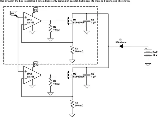
simulate this circuit – Schematic created using CircuitLab
If you have any ideas as to how i can get rid of the oscillations, please tell me. When i tested the circuit by it self i found C1 and R2 necessary to keep it from oscillating. If you need further information, just say so and i will update the question.
In advance, thank you!
