4

I have a load cell whose resistance is varying between 318.0 and 318.8 Ohm. I have used a voltage divider but still the output voltage is rarely changing when the resistance changes.

Is there any electric circuit that I can use in order to model the resistance variation in terms of Voltage variation?

stevenvh
  • 145,145
  • 21
  • 455
  • 667
roy
  • 41
  • 2
  • How are you measuring the output so that on the one hand you can say the resistance changes from 318.0 to 318.8 Ohms, but on the other hand you say "the output voltage is rarely changing."? – The Photon Jul 31 '12 at 04:04
  • @Roy, how do you measure the voltage? Multimeter? or ADC? – JeeShen Lee Jul 31 '12 at 04:50
  • Whatever solution you build, you're going to have to keep it temperature-stabilised. (How do you know the resistance is changing in the first place, BTW?) – pjc50 Jul 31 '12 at 10:25

2 Answers2

6

If the resistance change is indeed so small (which I doubt; it's only 0.25 %), then you need a Wheatstone bridge:

enter image description here

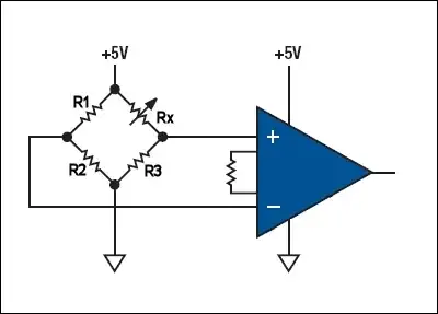
The amplifier is an instrumentation amplifier, so the feedback is internal. Rx is your variable resistor, and R3 is a fixed 318 Ω resistor. R1 and R2 are equal, their actual values are not that important, let's pick 10 kΩ for them. Then the voltage at the inverting input of the instrumentation amplifier will be 2.5 V, while the voltage on the non-inverting input will vary between 2.5 V (Rx = 318 Ω) and 2.497 V (Rx = 318.8 Ω). That's only a 3.14 mV difference, and you'll need a 1000 \$\times\$ gain to get 0 V to 3.14 V out of this.

The 0.25 % variation is smaller than the tolerance of a 1 % resistor, and even 0.1 % resistors will give you a noticeable offset. If you pick 0.1 % resistors for R1 and R2 then the theoretical 2.5 V may deviate by as much as 2.5 mV, that's 80 % of your full range. So you'll have to trim the resistors so that the output is 0 V at a 318 Ω resistance.

enter image description here

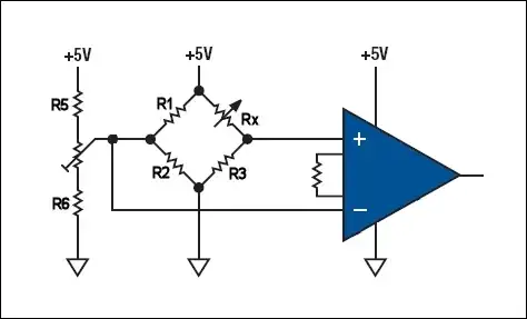
If you use 100 kΩ resistors for R5 and R6 and a 10 kΩ multiturn for the potmeter you'll be able to adjust the reference voltage between 2.48 V and 2.52 V.

stevenvh
  • 145,145
  • 21
  • 455
  • 667
  • 1
    What do you think of [this product](http://www.alternatezone.com/electronics/ucurrent/uCurrentArticle.pdf) that has been shared in chat before? It seems pretty awesome if it does as promised and looks okay to build. – Kortuk Jul 31 '12 at 06:24
  • @Kortuk - Not sure this is a solution. You get a voltage proportional to current proportional to resistance, then the voltage will also have that very small variation of 0.25 % of full scale. The Wheatstone bridge basically subtracts that high offset, so that instead of a 0.9975 to 1.0000 range you have a 0 to 1 range. – stevenvh Jul 31 '12 at 11:06
  • since I have seen it suggested to a few people I thought I would suggest it as something to discuss. Might it have a high precision and low accuracy so that it is good for tracing out shorts? – Kortuk Jul 31 '12 at 11:11
  • Am I missing the negative feedback on your opamps or are those intended to be something different? – Kortuk Jul 31 '12 at 11:12
  • @Kortuk - The amplifier is an instrumentation amplifier, so the feedback is internal. Added to answer. Thanks for pointing it out. Suppose you convert the 318 \$\Omega\$ to 3.18 V and you measure that with a 12-bit ADC with 3.20 V reference voltage, then the whole range from 3.18 V to 3.188 V covers only 10 counts, that's less than 4 bits resolution, despite the 12-bit. – stevenvh Jul 31 '12 at 12:01
  • did not know that was the symbol, thanks! – Kortuk Jul 31 '12 at 12:03
  • @Kortuk - Actually it's the symbol for a PGA, Programmable Gain Amplifier, where the resistor sets the gain. Most integrated InAmps are packaged this way, sometimes with a couple of integrated gain resistors, so you can choose between x1, x10, x100. Yet in the schematic the InAmp is often [drawn as three individual opamps](http://upload.wikimedia.org/wikipedia/commons/thumb/e/ed/Op-Amp_Instrumentation_Amplifier.svg/400px-Op-Amp_Instrumentation_Amplifier.svg.png), two buffers for the inputs, and one differential amplifier. – stevenvh Jul 31 '12 at 12:09
  • @stevenvh, I was thinking about this problem a few years back, where the sensor resistance change is small but might also drift over time, temp, etc. What I was thinking about, but never pursued, was the simplest extension of the circuit you describe that would null out long term drift or slow periodic drift. I believe I'll take a look at that problem again. – Alfred Centauri Jul 31 '12 at 23:18
2

Just to add to stevenvh's answer...

He mentioned that you have to trim the resistors in the bridge very accurately, and this is true. However, there are a few ICs specifically designed for this sort of application. For example, we use the AD8556. This is an instrumentation amplifier which has both programmable gain, and a programmable DC offset.

This lets you be a little more sloppy with the bridge resistors. You'll need to use a microcontroller to program the settings in the amplifier, but, once that's done, you also have the option to burn those settings into it permanently, so you can ship your product without the microcontroller if you need to.

Rocketmagnet
  • 26,933
  • 17
  • 92
  • 177