For a more precise measurement of a battery voltage I'd like to apply auto adjustment. The input voltage ranges from 2.5V-4.2V (single cell) to 20V-72V (module). At the moment the input voltage is divided by ~30 with a differential OpAmp and fed into a 24bit/512kSPS ADC (ADS127L01).
Since the voltage for single cells does only use a fraction of the full scale range I'd like to adjust the circuit. During my research I found a rather promising solution: http://www.electronicdesign.com/test-measurement/optimize-high-voltage-measurements-self-adjusting-attenuator
I built the schematic with LTspice and simulated the desired output voltage which looks quite good. Nevertheless, I'm not quite sure because the diodes are not simulated correctly. Can anybody explain how this should work? As soon the corresponding OpAmp saturates (eg. -5V), the voltage at the negativ input pin increases and can cause damage to the OpAmp as it exceeds the positiv voltage supply. How should this be avoided by the two diodes in parallel to the resistor?
How about accuracy? I also run a noise analysis in spice but as I said, I highly doubt the results are correct. The result would be around 10nV/sqrt(Hz) for the sample rate of ~500kSPS. Is it recommended to apply aditional differential filters, also to match with the differential inputs of the ADS127L01?
Furthermore, I have a question on extending this circuit for even higher voltages up to 1000 V. If I use R4 (eg. 10Meg) and adjust all other resistors so that the stages match with ranges of eg. 100V-300V, 300V-600V and 600V-1000V this should work as well?
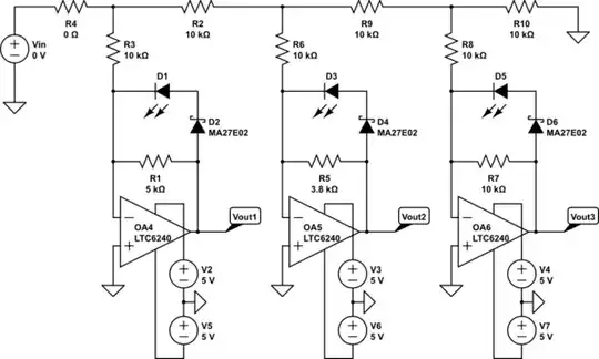
simulate this circuit – Schematic created using CircuitLab

I'm looking forward to your replies!