1

I tried to detect 220V AC in my microcontroller using SFH620A-3 with series resistance of 440K (2 x 220K, 1/4 watts SMD type), a 1uF at the output to smoothen the pulse and every works as expected. However the resistors produces good amount of heat specifically when placed in a closed enclosure. The heat is not high to start a fire (I can still touch), however the heat slowly propagates across the PCB and other components too get hot. I did the power calculations and the voltage across the opto is less that 1mA and the power dissipation is 130mW on each resistor. I may have multiple AC detection circuit on a single board and hence the heat would multiply.

  1. Is it a good practice to increase the resistance further? I tried some 800K and the output wasn't reliable.
  2. Are there other ways to reduce the heat ?
  3. Should I try another AC optocouplers ? If yes, can someone suggest some AC optocouplers (DIP-4 casing).

Schematics

schematic

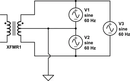
simulate this circuit – Schematic created using CircuitLab

Note : Transformers wont be feasible due to the size.

Update

I tried increasing the resistance by 100K, 50K etc and found that the opto fails to work at around 900K. The output seems to be stable at 770K, hence can I safely use 660K for my project (i.e 330K x 2) ?

Zac
  • 422
  • 1
  • 6
  • 15
  • What is the power rating of your resistors? You could use a 1/2 or 1 Watt device and elevate it above the board. Still the same thermal load, but not as concentrated as with a smaller power device, so the temperature of the resistor won't rise as much. – AlmostDone Apr 08 '18 at 20:42
  • I am using 1/4 watts SMD resistors. – Zac Apr 08 '18 at 20:45
  • With SMD resistors, you can lower the temp by increasing the copper trace width attached to the pads. In effect, the copper acts as a heat sink, spreading the thermal energy over a wider area which reduces hot spots. – AlmostDone Apr 08 '18 at 20:53
  • 2
    Use a capacitive dropper. It uses the reactance of the capacitor to drop voltage without generating lots of heat. Lots of articles on the internet. – Steve G Apr 08 '18 at 21:09
  • @SteveG Could you recommend the values for the capacitor ? – Zac Apr 08 '18 at 21:13
  • I tried with a 330K x 2 resistors (i.e total 660K) and it still seems to work fine. However I doubt about any false triggers as the current to opto is very limited. – Zac Apr 08 '18 at 21:57
  • The only other think I can think of is a neon-based optocoupler. These use a neon lamp and an LDR. But they tend to be quite large when packaged, and are deeply obscure. The only ones I found on a quick Google search are for vintage Fender amplifiers. – Simon B Apr 08 '18 at 22:26
  • hack an LED night light – jsotola Apr 08 '18 at 23:21
  • @Zacson you should calculate the value. – user253751 Apr 09 '18 at 01:29
  • @jsotola LED night light usually uses a resistor and a diode and they produces heat. – Zac Apr 10 '18 at 05:16
  • @immibis I needed help with the calculation, hence asked. – Zac Apr 10 '18 at 05:17

2 Answers2

3

You could add a capacitor in series with the resistors (a capacitor on each side, for safety reasons). If its capacity is adequate, it's impedance will drop a significant voltage without dissipating power (except a tiny amount due to its ESR).

Be sure to use mains-rated AC capacitors "X-type capacitors". Those have a "self-healing" structure that will prevent nasty failures in the case a line spike exceeds the capacitor voltage rating.

If most of the voltage is dropped on the caps you can lower the resistors by several order of magnitude (better to keep them anyway for safety, in case one of those spikes occur).

More details can be found in this other EE.SE thread.

  • As per the thread a 100nF capacitor seems to be fine, however 220V AC rated capacitors are huge and very expensive. – Zac Apr 08 '18 at 21:51
  • @Zacson - what do you call very expensive - a dollar or two? – Simon B Apr 08 '18 at 22:24
  • 1
    @SimonB comparing the price of these capacitors against the resistors, they are quite expensive. However this may be the solution which generates no heat. – Zac Apr 08 '18 at 22:33
  • @Zacson What are your cost constraints? Again you didn't specify an important information. Is this is for an hobby project or a professional solution. Keep in mind that when dealing with mains AC safety measures are paramount. Do something wrong and you may kill yourself or someone else! – LorenzoDonati4Ukraine-OnStrike Apr 09 '18 at 06:49
  • @Zacson X-rated capacitor are more expensive and bulky because they are certified and rated for very safe mains operations. In your case if you used a normal capacitor rated for 240Vac you could be in trouble if a 2000V spike appeared on mains. That could make the capacitor fails short and this would mean that 240V will appear across your low value resistor and optocoupler input. That could provoke a catastrophic explosion and even arcing over, with possible fire in the equipment. – LorenzoDonati4Ukraine-OnStrike Apr 09 '18 at 06:52
  • @Zacson IANAL, but in some legislations connecting any apparatus that is not conforming to safety regulation to mains is illegal. You could get away with a non-conforming apparatus in your private household ***as long as no accident happens***, and this means that some kind of safety measures should be designed in. Using X-rated caps is the minimum you could do to show a level of due diligence in case of an inspection. – LorenzoDonati4Ukraine-OnStrike Apr 09 '18 at 06:56
  • @LorenzoDonati Thanks for the information. I am trying to build a professional solution. Regarding the safety capacitors, what I have found appropriate is this - http://www.farnell.com/datasheets/2138222.pdf?_ga=2.47309859.50219854.1523251658-790306462.1508240417 – Zac Apr 09 '18 at 10:24
  • @LorenzoDonati Can I use just one of these capacitors for 6 optocouplers ? Lets say the capacitor is connected in series with the neutral terminal entering all optoisolator and the other leads have a resistor in series to the switches. In such case what should be capacitor value? – Zac Apr 09 '18 at 10:28
0

You could add a small step-down transformer at the input side, bringing down the mains voltage to, say, 5V, then use a single much smaller limiting resistor to power the input side of the optocoupler.

You will stop having so much heat to get rid of.

  • Transformer does not seems to be feasible due to the size. – Zac Apr 08 '18 at 20:43
  • 1
    @Zacson you didn't mention any size constraints in your question. You should add any relevant information and constraints, otherwise we could keep giving you good advices than turn out to be infeasible due to some constraint that you haven't specified in advance. – LorenzoDonati4Ukraine-OnStrike Apr 08 '18 at 20:51
  • Sorry for that. I have added the size constraint now. – Zac Apr 08 '18 at 20:59