6

In his answer detailing the various types of input pins, Russell McMahon leaves the following note [referring to input pins]:

there are special cases where a resistor to high and low at once is useful

What are the special cases where both a pull-up and pull-down resistor are required? Isn't there a current waste?

Randomblue
  • 10,953
  • 29
  • 105
  • 178

3 Answers3

10

I've done it several times when I couldn't figure out in advance which I really need. So I would put both on the PCB and only solder down one. In this way, if I was wrong I can just remove the resistor and solder the other one down.

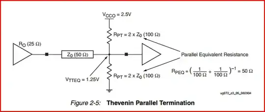
These days, split termination isn't done so much but it used to be a popular form of signal termination. To the unfamiliar, split termination looks like both a pullup and pulldown where the resistor values are usually less than 400 ohms.

For analog inputs, sometimes an input needs a DC bias. This can be done using a simple resistive voltage divider-- which also looks like a pullup+pulldown. Normally in this case there is also something that blocks the DC, like a cap in series with the signal, before the resistors.

In my opinion, you never actually need a pullup and pulldown at the same time, since it just doesn't make electrical sense. Using both at the same time will create a conflict and the end result is not an up or down, more like a pull-sideways! :) But there are lots of things, like the 3 that I mentioned, that will appear like a pullup and pull down at the same time. These are very common, and I know of new engineers who confuse them for pullups+pulldowns.
  • 1
    I had written an answer about split termination and was making circuits to try to make it more clear, you just saved me tons of time! – Kortuk Jul 28 '12 at 14:12
  • Split termination is prescribed by the VME standard... – vicatcu Jul 28 '12 at 16:22
  • @vicatcu Yeah, that's why said it isn't done so much anymore but was popular before. Remember that VME was invented in the late 70's (standardized in the early 80's). These days, split termination is rarely done. –  Jul 28 '12 at 16:36
7

The split termination mentioned can be used to make it easier for the output driver to reach OH and OL levels, by biasing somewhere in between. The parallel combination is set to the desired terminating impedance (e.g. 100 || 100 = 50 ohms)

Split Termination

With many modern chips, for standards like HSTL the termination is done internally. There are so many standards it can get a bit confusing at times, but there is usually plenty of documentation for use with your specific chip, for example here is an (oldish) Xilinx Virtex-4 PCB designers guide which mentions various standards and termination methods.

Also this link from one of the references in the link in David's answer provides a good explanation of why termination voltage can be important. The example shows a Virtex-4 HSTL driver hence the mention/link above.

Oli Glaser
  • 54,990
  • 3
  • 76
  • 147
  • 1
    That's the great thing about standards: There are so many to choose from! :) –  Jul 28 '12 at 16:36
  • 1
    Yep, great fun... :-) – Oli Glaser Jul 28 '12 at 16:50
  • 1
    This is what we call "voltage divider" and we used to do that to feed the base of a transistor. – Celal Ergün Jul 29 '12 at 11:14
  • Would there be any functional disadvantage to using a 50 ohm resistor to a capacitor-bypassed 1.25-volt reference generated using an op amp or other such device? – supercat Jul 29 '12 at 22:55
  • @supercat - no, it should look the same to the driver. This method is used also, SSTL in DDR is an example - have a read of [this article](http://www.eetimes.com/design/memory-design/4216279/Powering-DDR-memory-and-SSTL-logic?pageNumber=1) (linked to page 2 as most relevant). Also this [app note](http://www.fl-eng.com/_lib/pdf/ddr/signaling.pdf) – Oli Glaser Jul 30 '12 at 00:02
  • @OliGlaser: I wonder if there's any cheap but reliable way of designing a circuit which could resolve a low/high/floating input, but would draw essentially zero current in the floating case. If VDD is precisely known, one might use a PNP transistor with a string of diodes in series with the base to detect a "low", and an NPN with a string of diodes to detect a "high", but if VDD exceeds the voltage drop of the PN junctions both transistors would turn on and current draw would increase severely. – supercat Jun 07 '13 at 18:49
0

Providing so called Pull up & pull down resistors at same time is just like you are providing a steady state dc voltage input to the pin. If it is an analog input pin it may be useful but as far as digital input pin is concerned is not required. Either one of the two is required as per input condition. Modern day controllers have them inbuilt so that you can choose any one of them from software.