0

This link states that when determining the power needed by an amplifier, you use the following formula: enter image description here

I understand that the second term is due to the quiescent draw of the amp, but how is the first term derived? Where does the pi come from? I would have imagined it would be Vopeak^2 / R_L, since that is the peak power into the speaker.

Billy Kalfus
  • 1,021
  • 1
  • 7
  • 23
  • The Half cycle average value for a sinewave is \$\frac{Vpeak}{\pi}\$ So for the ideal class-B amplifier and the average supply current is \$\frac{V_{CC}}{\pi R_L}\$ – G36 Apr 04 '18 at 18:58
  • So then wouldn't the average output current be \$\frac{2V_{opeak}}{\pi R_L}\$ ? and why times \$Vcc\$? Because \$Vcc \neq Vopeak\$ due to voltage swing – Billy Kalfus Apr 04 '18 at 19:02
  • I made an error \$\frac{2}{\pi}\$ is the average for a sinewave and the average for a half-cycle is Vcc/(pi*RL). And Psupply = (Vcc+|VEE|)*Iavr = 2*Vcc(Iavr + Idc) – G36 Apr 04 '18 at 19:14
  • But the average value of a sine wave over a half cycle is \$\frac{2 V_{peak}}{\pi}\$. Divided by \$R_L\$ gives the current, then times \$2 V_{cc} \$ gives the power. So shouldn't that term have an extra factor of 2 for an overall factor of 4? – Billy Kalfus Apr 04 '18 at 19:22
  • Ah yes, \$\frac{2V_p}{\pi R_L} \$ the average supply current is. So, the avrage power delivered by the Vcc only is \$ V_{CC}*Iavr = 2 V_{cc} \frac{V_p}{\pi R_L} \$ – G36 Apr 04 '18 at 20:00

1 Answers1

2

Given \$\theta=\omega\:t=2\pi f t\$, just make \$\omega=1\$ for convenience.

Then \$\theta=t\$ and \$V_O=V_\text{PEAK}\cdot\operatorname{sin}\left(\theta\right)\$ and we can compute the upper quadrant power as:

$$\begin{align*} P_\text{UPPER}&=\frac{1}{2}\frac{1}{\pi}\int_0^\pi\left(V_\text{CC}-V_O\right)\frac{V_O}{R_\text{LOAD}}\:\text{d} \theta \end{align*}$$

The \$\frac{1}{2}\$ in front of that is because the power computation is for average power and the upper quadrant only operates for half of an entire cycle and will be zero power for the other half.

The lower quadrant will have the same figure as above (where \$V_\text{EE}=-V_\text{CC}\$.) So the total power of both quadrants added together is:

$$\begin{align*} P_\text{UP+LO}&=\frac{1}{\pi}\int_0^\pi\left(V_\text{CC}-V_O\right)\frac{V_O}{R_\text{LOAD}}\:\text{d} \theta\\\\ &=\frac{1}{\pi}\left[\frac{V_\text{CC}\cdot V_{PEAK}}{R_\text{LOAD}}\int_0^\pi \operatorname{sin}\left(\theta\right)\:\text{d} \theta-\frac{V_{PEAK}^2}{R_\text{LOAD}}\int_0^\pi \operatorname{sin}^2\left(\theta\right)\:\text{d} \theta\right]\\\\ &=\frac{1}{\pi}\left[\frac{V_\text{CC}\cdot V_{PEAK}}{R_\text{LOAD}}\cdot 2-\frac{V_{PEAK}^2}{R_\text{LOAD}}\cdot\frac{\pi}{2}\right]\\\\ &=\frac{2\cdot V_\text{CC}\cdot V_{PEAK}}{\pi \:R_\text{LOAD}}-\frac{V_{PEAK}^2}{2\:R_\text{LOAD}} \end{align*}$$

The power in \$R_\text{LOAD}\$ is obviously \$\frac{V_{PEAK}^2}{2\:R_\text{LOAD}}\$, so adding that to the above provides:

$$\begin{align*} P_\text{TOTAL}&=P_\text{UPPER}+P_\text{LOWER}+P_\text{LOAD}=\frac{2\cdot V_\text{CC}\cdot V_{PEAK}}{\pi \:R_\text{LOAD}} \end{align*}$$

The only remaining addition is to add the quiescent power and I think you already agreed about that part of the computation so I won't belabor it here.


Notes:

Audio amplifiers typically operate in class-AB. Also read a very general description of the different classes of operation for an amplifier and the meaning of quadrant as I was using it above.

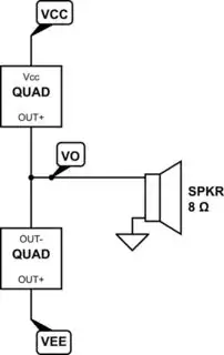
In class-AB, the basic amplifier block diagram would look something like this:

schematic

simulate this circuit – Schematic created using CircuitLab

From this, you can see that when \$V_O\$ is positive the lower quadrant is OFF and only the upper quadrant is ACTIVE. Similarly, when \$V_O\$ is negative the upper quadrant is OFF and only the lower quadrant is ACTIVE. To compute the average power for the upper quadrant, you have to take into account that it is only active for half a cycle. During the other half, it's OFF so there is no power dissipation during that half-cycle. So the average power for the upper quadrant over an entire cycle is one-half of the average power during its ACTIVE period. Similarly, for the lower quadrant.

Because it is class-AB and not precisely class-B, there is a quiescent current flowing between the upper and lower quadrants when \$V_O\approx 0\:\text{V}\$ (when there is no current in the speaker/load.) Since this current flows all the way through, from \$V_\text{CC}\$ to \$V_\text{EE}\$, you have to also account for that addition. There are several important reasons (cross-over distortion and thermal stability being a couple, but which may include others depending on the exact design) for including this quiescent current. It's not uncommon for this to amount to 5-10% of the rated power for the amplifier, but this percentage may also vary depending on the maximum power rating too since there are several factors being accounted for and no simple rule to follow. Regardless, it's worth accounting for it.

jonk
  • 77,059
  • 6
  • 73
  • 185
  • Thank you for such a thorough explanation! One thing I'm still a bit confused about - when you have the factor of 1/2, you say it's for the fact that we are only integrating over half a cycle. But isn't that already accounted for by the bounds of integration and the 1/pi? – Billy Kalfus Apr 04 '18 at 21:27
  • Also, where does the Vcc - Vo factor come from? – Billy Kalfus Apr 04 '18 at 21:28
  • @BillyKalfus No, it's not. The problem here is that you need to keep in mind that the "average power" that this equation computes is "the average for one-half cycle." During the other half-cycle the power is zero (not shown in the equation.) So the average needs to be divided by 2 to get the average over the ***whole cycle***. Or, perhaps, I should have just used \$\frac{1}{2\pi}\$ in the first place so that it was for the entire time of a cycle. Either way, same thing. – jonk Apr 04 '18 at 21:46
  • okay, that makes sense - why is it zero during the second half-cycle? – Billy Kalfus Apr 04 '18 at 21:49
  • @BillyKalfus The \$V_\text{CC}-V_O\$ comes from the fact that the quadrant ONLY needs to drop that much voltage, because the load itself drops the rest. So the voltage across the quadrant is the difference. – jonk Apr 04 '18 at 21:49
  • True, but isn't this formula for the power being consumed by the load? Or is this just the power dissipated by the amp when supplying power to the load? – Billy Kalfus Apr 04 '18 at 21:50
  • @BillyKalfus Sounds like I need to add pictures and stuff. Have you read what I wrote here: [amplifier quadrants](https://electronics.stackexchange.com/questions/364315/confusion-between-class-b-and-class-ab-amplifier/364320#364320)? Do you know what class-AB operation is? – jonk Apr 04 '18 at 21:52
  • Just read it - makes sense, so the power is zero during the second quadrant due to the topology of the class AB amp. So the the formula here calculates the power dissipated by the amp (because of the voltage drop from Vcc to Vo), then at the end you add the power dissipated from the load, then (as I mentioned above) you add the quiescent power all together to get total power dissipation - is this breakdown correct? – Billy Kalfus Apr 04 '18 at 21:57
  • @BillyKalfus Yes, that's pretty well described. I added some helpful discussion at the bottom now and included a link you can go to for the meaning of *quadrant* as I used it. (I'm not sure you understand that term from seeing you use it here in your comment.) – jonk Apr 04 '18 at 22:09