1

First time posting, totally new to electronics so please go easy on me.

I have a circuit made up of two smd leds with two seperate live feeds and grounds that switch from one to another using npn transistor. It all works perfect when tested on bench and 12v supply. But once connected in the car it seems that the second feed that when once on should kill the first led has constant small current running through it and immediately switching off the first led without being fully activated. I hope that makes sense? Ive put a multimeter on it and it seems to read just below 0.8V in off position which possibly is enough to disable the first led instantly? The first feed is illumination feed, second is interior light circuit connection.

Is there anything I can add to the circuit to have it working as I want it?

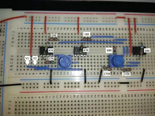
This is the schematic which works fine on bench with 12v supply

enter image description here

So red led gets power and is on. As soon as white led gets power it switches off the red one. Once the white led stops getting power the red one comes back on.

It’s all good when two 12v feeds are supplied on bench. But once connected in the vehicle as soon as the wire for white led is connected but not activated it knocks off the red one instantly. The white led feed comes from interior light circuit from body control module so once the door opens etc it activates the led but somehow the feed isn’t 0v when it should be off hence the red led deactivation?

Thank you for any guidance and info on this.

Apologies for not making it very clear

Stanley

stanley
  • 19
  • 2
  • Welcome! How do you switch it off? Just below 0.8 V sounds suspicious like one diode drop rectifying something for you. Do you have a schematic or block diagram? – winny Mar 29 '18 at 08:19
  • 1
    schematic or it didnt happen – PlasmaHH Mar 29 '18 at 08:39
  • "*So red led gets power and is on. As soon as white led gets power ...*" There is no mention of red or white in the schematic. Use component designators "D1" and "D2" instead. Same with "*should kill the first led*". Is this D1 or D2? I think a major tidy up of the text would help. – Transistor Dec 07 '19 at 08:33

2 Answers2

1

This is not a complete answer yet but may help clarify your problem.

schematic

simulate this circuit – Schematic created using CircuitLab

Figure 1. OP's circuit redrawn with convention of current flow from top to bottom.

Schematic diagrams should be laid out to reveal the schema of the circuit as clearly as possible. Yours manages to conceal it very well with LEDs pointing upwards, unnecessary kinks crossovers and poor component placement. See Rules and guidelines for drawing good schematics for some excellent guidance on this topic. With the schematic redrawn in a conventional manner it becomes obvious that Q1 is upside-down and won't work as I think you expect.

Normally an indication circuit like this would have the LEDs connected to a common ground rail or a common positive rail. With all four inputs floating and no indication of what supplies 1, 2, 3 and 4 it is impossible to analyse the circuit operation.

Transistor
  • 168,990
  • 12
  • 186
  • 385
0

put a resistor to ground on the second feed.