I want to protect a pin with an opto isolator to get an external signal from an electrical meter (35VDC max, 50mA max, 240ms pulse width). The purpose is to count the pulses.
Do you have some schematics examples for that ?
Thanks
I want to protect a pin with an opto isolator to get an external signal from an electrical meter (35VDC max, 50mA max, 240ms pulse width). The purpose is to count the pulses.
Do you have some schematics examples for that ?
Thanks
This shouldn't be too hard:
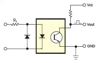
Vcc is the +5 V Arduino power supply, Vout goes to an I/O pin.
Important parameter for an optocoupler is its CTR (Current Transfer Ratio), comparable to HFE for a transistor. But where HFE is often around 100 for a general purpose transistor, it's often less than 1 for an optocoupler, and therefore often expressed as a percentage, like CTR = 50 %, which means that you get 5 mA out for 10 mA in.
You seem to have enough current available, but we won't need it all. The CNY17-2 has a CTR of 22 % min at 1 mA input, so we can get 0.22 mA out. The Arduino works at 5 V then the pull-up resistor should be minimum 22.7 kΩ to allow the transistor to pull the output low. You can even go higher but then you'll have to keep an eye on the transistor's leakage current. The CNY17-2 has a low 50 nA for that, so that won't cause any trouble. There's also a maximum 1 µA leakage into the AVR controller, but even that will only cause a 100 mV drop with the transistor off, so that's safe.
The 100 kΩ also would mean that you only need 50 µA output current to pull the output low. At 1 mA input we had 220 µA out, so everything is peachy. For 35 V input and a maximum voltage drop across the LED of 1.65 VR1 should be maximum 33 kΩ.
You'll have to check what the current will be at the minimum input voltage with this resistor value. For instance if the input voltage can be as low as 12 V then you need maximum 10 kΩ.
The anti-parallel diode protects against reversed connection, and can be any diode, like a 1N4148.
Note: Darlington output optocouplers like Oli's 4N32 have a much higher CTR, but it looks like we can do without that, and Darlington devices are more expensive: the 4N32 is twice as much as the CNY17.
If you google "MCU pin optoisolator" or similar you will get many pages with information about how to do this.
A typical circuit:
The optoisolator can be anything similar to the one shown. If you know the voltage you wish you read, and look in the datasheet for the typical operating current for the input diode, you can size R1 appropriately.
For example say the Vf for the diode is 1.2V, your voltage is 35V and you wish to have a diode current of 10mA:
(35V - 1.2V) / 0.010A = 3380 Ohms.
D1 protects the opto input diode against reverse voltages, since they con usually only stand a few volts reverse before they die. If your 35V source is likely to produce the odd negative spike (e.g. AC/inductive) then this is a good idea - even if it's not, it doesn't hurt to have it there just in case.
On the transistor side, 1k to 100k will do in most cases.