I apologize for not noticing and also for not reading perhaps as long or as well as I should. I'll just quickly think through some thoughts.
- Your \$R_2=22\:\Omega\$ suggests to me an LED current of about \$32\:\text{mA}\$ or less.
- The threshold voltage for that FET is a max of \$2.45\:\text{V}\$. Add to this a \$V_\text{CE}\ge 1\:\text{V}\$ (to stay well out of saturation), I'd say that \$V_1\ge3.5\:\text{V}\$.
- However, you don't want a lot of variance of \$Q_1\$'s \$V_\text{BE}\$, so this means the collector current should be relatively stable. So a current source would be optimal instead of \$R_1\$.
- Lacking a current source and instead stuck with a resistor there, this means that the voltage drop across the resistor needs to be limited to an acceptable dynamic range. Let's pick the range from \$1\:\text{V}\$ to \$4\:\text{V}\$.. this would imply a range in the \$V_\text{BE}\$ of \$26\:\text{mV}\cdot\operatorname{ln}\left(\frac{4}{1}\right)\approx 36\:\text{mV}\$. Across the resistor of \$R_1=22\:\Omega\$, this implies less than \$2\:\text{mA}\$ variation in the LED current.
- So now, \$4.5\:\text{V}\le V_1\le 7.5\:\text{V}\$, with still higher maximum voltages implying even more LED current variation.
- So if we assume a starting collector current for \$Q_1\$ of \$1\:\text{mA}\$, then \$R_1=\frac{1\:\text{V}}{1\:\text{mA}}=1\:\text{k}\Omega\$. The exact value you have in your circuit.
- Base current of \$Q_1\$ should stay below \$\frac{4\:\text{mA}}{\beta=100}=40\:\mu\text{A}\$, which is modest compared to the LED current and shouldn't significantly impact it.
So I actually don't see a problem. So long as your starting voltage is at least \$4.5\:\text{V}\$.
If you'd used a fixed voltage (say \$5\:\text{V}\$) at the top of \$R_1\$, that would just be even better, really.
Either way, I think it should work.
So I'm not sure about the problem. Current source would be better. But the resistor, assuming some reasonable limitations on the lowest allowable voltage, should be okay. Not optimal. But okay.
So if you are experiencing odd behavior, I'd look more closely at the devices themselves (make sure they are good) and also the wiring. Something else is going on.
An approach that is relatively stable over temperature, works passably vs supply voltage, and uses the same number of active parts, you could consider this:
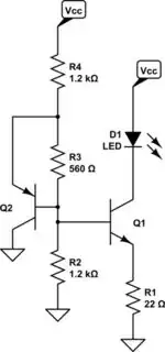
simulate this circuit – Schematic created using CircuitLab
The temperature stability applies if both BJTs are coupled thermally. If the temperature increases, the \$V_\text{BE}\$ of \$Q_1\$ declines, leaving a higher voltage across \$R_1\$, and this fact would tend to suggest that there would be an increase the LED current. However, as the temperature increases and assuming that \$Q_2\$ is thermally coupled to \$Q_1\$, then this also means that \$Q_2\$'s \$V_\text{BE}\$ declines and therefore there is less current through \$R_3\$ and thus also through \$R_2\$. With a now lower voltage drop across \$R_2\$, the base of \$Q_1\$ is lower too. So this tends to compensate by causing a smaller voltage drop across \$R_1\$.
It uses just two BJTs. The cost is in the added resistors. Also, cheap BJTs can be used. I get my BJTs for far less than I get my FETs for, generally speaking.
