I'm studying recently Electric Circuits (9th edition) by Nilsson. In Chapter 2, an example bothers me.

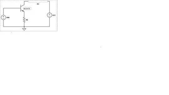
simulate this circuit – Schematic created using CircuitLab
I don't understand why these above figures can't be permissible. (I know KVL and KCL, but I want to analyse these circuits with another physical meaning.)
In addition, I want to know what situations will appear in these circuits.