29

I am fairly new to "electrical" engineering as a hobby/ past time. I have always loved electricity and have made simple circuits since I was a little baby.

I am now working on one of my first arduino projects and I started thinking about what color wires I should use for the different I/O and serial communication.

I know it doesn't matter, but I am curious: are there standard wire colors for things such as Tx and Rx, Digital IO, analogue IO?

It is very common that Red is "Positive" and Black is "Negative." I have also noticed that USB data wires are usually green and white. Are there other standards that are commonly used for other applications? Can someone give me a list please?

Sponge Bob
  • 5,193
  • 16
  • 46
  • 64

5 Answers5

22

Obligatory link to the XKCD comic about standards:

Fortunately, the charging one has been solved now that we've all standardized on mini-USB. Or is it micro-USB? Shit.

So yeah, there are standards. There are so many of them that it's effectively the same as having no standard, as every possible wire arrangement likely has a standard that describes it.

Connor Wolf
  • 31,938
  • 6
  • 77
  • 137
13

There's no single standard everyone would refer to, but there are two common systems - one was introduced by DIN (DIN 47100), the other one borrows from the system you may know from resistor color codes (in this context sometimes referred to as UL/CSA):

Wire Color Schemes, DIN 47100 and UL/CSA

Note that DIN 47100 allows to arrange the wires in pairs; you will often find 1/2 (wht/brn), 3/4 (grn/yel), ... as twisted pair arrangements.

Sometimes, you will find ribbon cables or other pre-made cables with colors in one of these versions. If you need more than 10 wires, combinations are used.

These standards apply for signal wiring. Supply wires for small voltage DC often use red for positive, black for ground and blue for negative. For power installations, other systems are in use and must be adhered to.

Blair Fonville
  • 3,837
  • 4
  • 19
  • 45
zebonaut
  • 18,170
  • 4
  • 60
  • 104
  • Your Medikabel PDF link seems to have gone the way of the Dodo, sadly. But I was able to find this page on their site, which will pop up various lightboxes (ugh, you suck JQuery) containing color-codings — in English, even! — for a whole range of standards (thereby also providing support for the accepted answer). It sounds like it covers at least the contents of that PDF, though the information is presented in a maximally inconvenient — though admittedly quite pretty (in the case of their own custom jacket/core colorings) — manner. http://www.medikabel.de/en/technics/colourcodes – FeRD Sep 17 '16 at 12:00
9

In electronics, red is usually positive power, black is ground, and the rest can be anything. It would be smart to avoid black or red for signals, but otherwise use what you have. Multiple signals with power and ground are often convenient to carry on a ribbon cable. In that case, you end up with whatever colors the cable has. Don't worry about it.

However, beware, at least here in the US the standard for the hot lead of electric power is black, neutral is white, and ground is green. If you install house wiring, you should follow this code (or whatever local code there might be in your jurisdiction) but never count on others having done so.

The best thing about standards is that there are so many to chose from ;-)

Olin Lathrop
  • 310,974
  • 36
  • 428
  • 915
4

Nope. With black and red you have mentioned the ones which are rather standard. But like the answers to this question say you sometimes can't even rely on black being ground. It's the jungle.

Best thing you can do when you start breadboarding is to use as many different colors as possible, so that you can tell them easier apart if the wiring would become a bit messy. At work I use a set of 10 different solid colors, and you may find two colored wires as well, which give you a lot more variation.

stevenvh
  • 145,145
  • 21
  • 455
  • 667
  • Power wiring has local standards that must be applied. At low voltages, it’s more of a convention, but do not mix the two. Within a breadboard, anything goes. But every external interconnect should follow a consistent approach. Document that carefully. – simon coleman May 22 '21 at 11:36
3

Indeed power red and black.

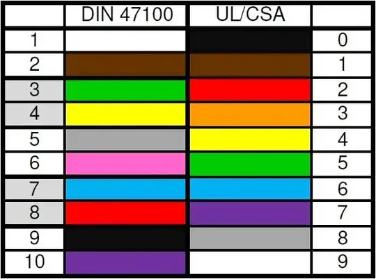
The colors wire I have available are similar to those used for color rings on resistors and what I usually do with Arduino's is using a color wire that corresponds with the pin number of the Arduino. In this manner it is relatively easy to see which wire is connected to which pin.

So pin number 0 => black; pin number 1 => brown; 2 => red; 3 => orange; 4 => yellow; 5 => green; 6 => blue; 7 => violet; 8 => grey; 9 => white; 10 => black (again ..., don't confuse with power); 11 => brown; 12 => red; ...

Same for analog input pins (A0, A1, ...).

Most of the time I have little trouble seeing the difference between red for power supply and red for pin 2 (same for black), because they come from an entirely different location on the Arduino. Also for power I like to use somewhat longer wires, which makes it easy to identify them too.

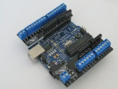
Many pins on Arduino have more than one function, which makes it difficult to identify a pin for eg. RxD as in your next project this pin can have an entirely different function. Personally I like the use of screw shields. I attach wires to Arduino ones and they seldom come off once connected. Many variation on the theme of screw shields exist. Some are more expensive than others, mine look like these

enter image description here

Personally I use this trick in many cases where I have to wire many connections. It is simple and easy to remember (once you know your color rings).

jippie
  • 33,033
  • 16
  • 93
  • 160