5

I'm trying to scope out what frequencies different common analog signals are. The DPScope design specs provides a list of common lower (sub 1 MHz) frequencies (copied below).

  • audio (20 kHz)
  • infrared remote control signals (38 kHz)
  • ultrasound (200 kHz)
  • servo signals (a few kHz)
  • bio signals, medical instruments (< 100 Hz)
  • I2C (1 MHz)
  • RS-232 (115 kHz)
  • one-wire
  • SPI (as long as <= 1 MHz)

However, some of those listed are used for transferring digital data (for example, RS-232).

Now my questions:

Under what situations would it be necessary to have a bandwidth capable of measuring these digital lines as analog signals?

What important analog signals (or digital signals that should be tested as an analog signal) have higher frequencies than those listed above?

helloworld922
  • 16,600
  • 10
  • 54
  • 87
  • The classic one that dictated 'scope design was NTSC (or PAL) video, needing apparently about 5 MHz. But its been a while since I looked at an NTSC signal, and its importance is fading fast. – The Photon Jul 20 '12 at 21:30
  • Ultrasound can easily get up to 10MHz in practical technology. – DarenW Mar 01 '13 at 05:17

4 Answers4

5

I assume "as an analog signal" means on an oscilloscope as opposed to a logic analyser.

For a digital signal, it is important to be able to check the signal integrity and see whether it is subject to problems such as ringing, crosstalk, reflections, jitter, attenuation, etc.

This can only be done with a scope with a bandwidth > the frequencies present in the signal - remember with a digital signal there are frequencies much higher than the fundamental present, how high is dictated by the rise time of the signal. For a 1MHz digital signal you would generally want at least a 5MHz bandwidth, preferably much higher.
For debugging a typical small microcontroller (e.g. PIC, Atmel AVR, Arduino, etc) a scope bandwidth of at least 50MHz is preferable. This should be capable of handling just about all situations you might encounter.

There are many signals above 1MHz that need checking, most microcontroller clock signals are > 1MHz, SPI is often > 1MHz, USB, etc. FPGA designs may run at 100s of MHz, high speed ADCs and DACs, etc.

On a logic analyser all you can see is whether it is above a certain level or below a certain level (like a 1-bit scope) so while useful in other ways they are not suitable for checking signal integrity.

The image below (taken on an MSO - Mixed Signal Oscillscope, a combination of a scope and logic analyser) is a good example of crosstalk causing problems and why a scope is needed to see what's really happening. Notice the waveforms are quite a way from the idea of a "perfect" digital signal:

MSO crosstalk

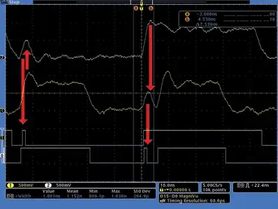
For the leftmost red arrow the second trace down is the transmitting trace, and the top trace down is the "victim" (receiving trace) and the right hand pulse they are reversed. We can see on the rise of the "transmitting" signal it causes a spike in the receiving trace, resulting in a unwanted glitch on the logic display, which is what the digital receiver would "see".

In this image at the top we can see signal degradation caused by an incorrectly terminated trace, causing reflections. At the bottom we can see the same signal after it has been correctly terminated:

Reflections

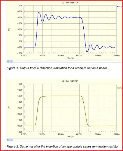
On the logic analyser, both signals may work, but there is no way of knowing how marginal the first signal is without checking with a scope. The incorrectly terminated trace may only cause problems intermittently, so it's important to be able to check it's integrity.

Looking at your link to the DPScope design, I see it's dsPIC based. It won't be comparable to anything you can buy (you can get a 20MHz analogue scope for << £50 nowadays, and a 5-10MHz DSO for similar)
However, it would be a great project for educational purposes, and you will get something perfectly useable for low frequency (e.g. audio, UART, PWM) purposes. Plus you'll have fun building it. If your thinking of doing so, I'd say go for it, just don't expect it to take care of all your debugging needs. If your budget is limited, get a cheap analogue scope - you will generally get the highest bandwidth for your money.
Remember the chicken and egg problem - you need a scope in order to build and test a scope ;-)

Oli Glaser
  • 54,990
  • 3
  • 76
  • 147
3

A rough rule of thumb is you want about 10 times the bandwidth as the frequency of the digital signal you want to see on a scope. This is assuming you want to see the wave shape, not just when it goes high or low.

Modern scopes have two issues related to bandwidth: The bandwidth of the analog electronics to receive your signal and present it to the internal A/D, and the sample rate of that A/D. Nyquist says you need at least 2x the sample rate of the highest frequency of interest. However, that is the absolute minimum theoretical. In practise you need usually a few times more than that at least.

Sampling aliasing of a scope gets annoying, and sometimes it can give you completely the wrong idea or really confuse you if you're not noticing that's what is happening. A sampling rate 10-20x the highest frequency the scope can handle is usually about right. Keep in mind that 2x is the guaranteed to fail limit. For example, a 60 MHz scope might have a sample rate of 1 GHz or so.

Olin Lathrop
  • 310,974
  • 36
  • 428
  • 915
-1

Q Under what situations would it be necessary to have a bandwidth capable of measuring these digital lines as analog signals?

A Debugging phantom errors in the presence of RF noise or EMI such power line transients, ESD events, RF power bursts and last but not least an EMP. Crosstalk is another source of interference and common to bundles of RS232 signals on multi-wire pairs.

So far all the other answers give correct info as well.

External data communication with unshielded twisted pair wires (UTP) is good but insome cases not enough to protect data from transient errors. Shielding can provide 40~60dB of reduction and filtering with magnetics can also reduce common mode noise, but you never eliminate analog noise all together. So it all digital signals are analog with sufficient margin that we treat them perhaps as binary signals most of the time.

Q What important analog signals (or digital signals that should be tested as an analog signal)

A I can list hundreds of communication serials signals that are considered digital that must be scoped as analog; but in general; Disk drives read / write data from heads, Telemetry receiver , I2C signals that fail in a shared access mode, Ethernet signals that cause high error rates, T1 repeaters, all optical data receiver links, DVD error rate debug testing. etc etc. Another is logic "race" conditions in which case a signal changes state just when it is being sampled by a clock.

Q have higher frequencies than those listed above?

A The fastest pulse I have seen is from a human finger discharging 10kV to a door knob. The rise time was 20 pS using an extremely fast scope 20 yrs ago. Plasma arcs arc caused by the tunnelling of electrons in a plasma state created when air breaks down by exceeding its dielectric withstanding voltage of usually 1kV per mm.


enter image description here

Recent photo from EOS/ESD experts.. still does not have enough bandwidth to capture the event, but is not bad at 336ps rise time.

http://www.analog.com/static/imported-files/quality_assurance/eos_esd_chapter_091400b_103.pdf

Tony Stewart EE75
  • 1
  • 3
  • 54
  • 182
  • 3
    To see a 20 ps (lowercase "s") rise time you need at least 500 GHz bandwidth. I'm not sure there were many scopes that fast 20 years ago. Also I doubt that you can attenuate 10 kV to the scope's input level without decreasing rise time. 10 kV in 20 ps is 500 000 000 V/\$\mu\$s. Are you sure your memory isn't failing you? – stevenvh Jul 21 '12 at 06:17
  • au contrair, When I was the representative to the Burroughs Corporate Standards for EMC I contributed to re-writing the test standards for Corporate wide EMC testing of PLT, EOS, ingress, egress, etc. I did my research back in the early 80's and by coincidence met a consultant who showed me the photo. He contributed to the ESD/EOS model for the standard test used today for Hand and Cart models or RC equivalent network and voltage with rise time. Today many companies make these Generators and it is an IEC/ANSI standard. He used a sampling osc. with a repetitive discharge. > go read – Tony Stewart EE75 Jul 21 '12 at 12:06
  • I can easily find many exmaples ... http://resource.npl.co.uk/docs/science_technology/electromagnetics/wireless_communications/ultrafast_flyer.pdf http://www.infineon.com/dgdl/AN210.pdf?folderId=db3a304313b8b5a60113d4239297042f&fileId=db3a30432cd42ee3012cee8d005b0c19 but to find the original photo in early 80's may take time. You are younger and have more time. The Ansi standard was slowed down so that ESD protection diodes could be fast enough to protect, but in reality worst case EOS/ESD is what I stated faster than clamp diodes proved by UK research. – Tony Stewart EE75 Jul 21 '12 at 12:08
  • YOu may forget but I have been on the bleeding edge of technology since 1975 in R&D with many world firsts. The name of the Swiss company that made the EOS generators based on this early model of 20 ps ,as I recall was a swiss schweizer generator in the early 80's but there, I could be mistaken on the spelling. – Tony Stewart EE75 Jul 21 '12 at 12:19
  • Here is another example that is relevant to the original question and one that I experienced when I tested HDD's at the head disk interface in 1982 at Burrough's, Memorex, and worked with all the experts in the world on disk drive design/mfg. Due to the tribo-lectric effect, disk drives can generate a lot of ESD unless they use conductive grease (ferro-fluidic) in the bearings and a copper ground brush to dissipate the static.. another good example of a when I used analog scopes back then... which is relevant today http://www.credencetech.com/products/more/New_EOS_Test_Recording_Heads.pdf – Tony Stewart EE75 Jul 21 '12 at 12:25
  • You will find in life that some people may not have enough bandwidth to comprehend, but that is ok, we are all here to learn. but 20ps is what you get when you arc with your keys to open a car door on a dry day, or walk across a nylon carpet with your neoprene shoes in a hotel.. You dont even need 25kV to get 20pS in fact lightning is not this fast but almost. **YOu need repetitive waveforms to capture on both a spectrum analyzer and a Sampling Oscilloscope** for 20 ps. I can discuss why and how in another carefully requested new question. – Tony Stewart EE75 Jul 21 '12 at 12:42
  • 6
    You don't have to be derogatorive. And don't try to impress me with all your fancy stuff, I told you before it won't work! You'd better try to make an impression with a really good answer. (And don't complain that users are too simple to understand your answers, they're not. It's just that most of your answers lack the quality to be good answers.) – stevenvh Jul 21 '12 at 13:16
  • 4
    Electric arcs thru air are not a tunneling phenomena. When the air breaks down it becomes a plasma, which has free electrons, which makes it a conductor. There is no tunneling, just ordinary conduction. Tunneling works over very short distances only, or more precisely falls off much much faster than linearly as distances in increase. Lightning would be impossible if it relied only on tunneling. – Olin Lathrop Jul 21 '12 at 14:54
  • ok stevenh but I disagree with well presented answers that appear to be high quality but are technically invalid or wrong.. and prefer answers that can be supported with missing assumptions overlooked by the incorrect answers.. Olin you need proof. May I suggest After his retirement from leading decades of hot fusion research at LANL, the late James Tuck (co-inventor of the Theta Pinch)took up the scientific study of Ball Lightning and published a review on the subject in Nature in the late 1960’s and a more comprehensive Los Alamos Report in 1971. – Tony Stewart EE75 Jul 21 '12 at 15:41
  • I assert those who are; open-minded to new information by asking questions, they are not ignorant, just uninformed and those who possess such experience are not arrogant when they share it freely. But when challenged by some that maybe uninformed and closed minded may be considered ignorant for being critical and not open minded to new information. I am open to new information and not closed-minded. If poking fun at "not having enough bandwidth" to see a fast rise time is derogatory and fail to ask how? ... then I apologize for trying to use humour. – Tony Stewart EE75 Jul 21 '12 at 15:43
  • Olin where did I state that Lightning ONLY relied on tunnelling. It is only a state that closes the gap after the arc occurs. The gap is inversely related to the spectral emissions and ESD has been proven to create spectral emissions far greater than lighting due to the smaller rise time. But it is not the gap of the lighting but, withing the arc itself after the capacitive/resistive dielectric breakdown threshold is exceeded. The smallest gap within the corona determines the fastest risetime. Search "Plasma Equation of State (Berlin-Montroll) lightning" – Tony Stewart EE75 Jul 21 '12 at 15:50
  • 5
    @Tony - An answer is no use if nobody can make heads or tails of it, no matter how correct it may be. I don't think you get downvoted because people think you're wrong, but because the answers aren't *clear*, and then the downvote means "not useful". And believe it or not, you can also be wrong. [This](http://electronics.stackexchange.com/a/35958/2064) is not a good answer because you don't seem to mind an AVR sinking 40 mA, *which may damage it*. Try some modesty, other users will appreciate it. – stevenvh Jul 21 '12 at 16:58
  • @Stevenh **Here** below[1] is another great example of how content gets judged by uninformed people by its format. I have dozens more examples if you like that will prove format gets more points than accurate relevant content from experience... Brevity often limits my explanations. If you dont understand ask.. dont just vote .. that action on a consistent basis is not uninformed.. it is ignorant of others to do so. [1] http://electronics.stackexchange.com/questions/30528/how-do-you-calibrate-32-768khz-crystal-for-pic24-rtcc/30578#30578 – Tony Stewart EE75 Jul 21 '12 at 22:05
  • 2
    @TonyStewart The problem is that your answers are often incorrect and usually communicated poorly. – W5VO Jul 21 '12 at 23:53
  • W5VO I find more errors in others answers that are nicely formatted.. and I consider many of the opinions negatively judged to be ill informed. Do not conclude base on poor experienced -ve points.. I can and will justify all the errors of others from now on. for example stevenh's answer on Raspberry Pi WIFI .. totally wrong solution to use LDO when the 700mA consumption exceeds USB port of 500mA... today... Do not confuse confidence with arrogance and I will try not to confuse other's ignorance with uninformed conclusions. – Tony Stewart EE75 Jul 22 '12 at 03:14
  • W5Vo show me one signifcant answer I gave that was incorrect with proof. – Tony Stewart EE75 Jul 22 '12 at 05:08
  • 2
    @TonyStewart funny thing... I've got one - the one where you said the community was wrong for downvoting you. Incidentally, you even proved that your answer was wrong in the comments. http://electronics.stackexchange.com/questions/30528/how-do-you-calibrate-32-768khz-crystal-for-pic24-rtcc/30578#30578 – W5VO Jul 22 '12 at 05:32
-4

I propose to you, that all digital signals are analog in nature and to fully understand issues of reliability, you need to understand all the analog equivalent circuits of digital signals. Recent google search just now showed the analog equivalent circuit I discussed in comments of an HDA part of a HDD with EOS discharge model from tribo-electric effect on moving disks under recording heads for magnetic recording.

We all think of disks as digital storage medium. Now neglecting the magnetic properties and just focusing on the OES/ESD properties of pico second discharge pulses, this is the equivalent circuit , some researchers have come up with. I was ware of this model in my mind back in the early 80's when I was Test Engineering Mgr at Burroughs/Unisys and we refurbished about 100 different old peripherals, built new and tested OEM HDD's for systems integration. So we had several Class 100 Clean rooms and many servo writers where we had to resolve these issues, such as the one modelled for Electro-Static-Discharge (ESD) in this photo.

enter image description here

Ref: http://www.credencetech.com/products/more/New_EOS_Test_Recording_Heads.pdf

this is old news to me... but a very good article. which reinforces the need for ANALOG SCOPES of digital signals that are very common to everyday life. (ESD)

Tony Stewart EE75
  • 1
  • 3
  • 54
  • 182
  • no comments means closed minded when -point added .. ok? I provided relevant proof. YOu are free to disagree without. ( in philosphy, may be considered bad form ) – Tony Stewart EE75 Jul 21 '12 at 15:56
  • 3
    It is suggested that users leave a comment but no requirement exists. I would say the less likely someone believes a user to take advice directly affects the chance that they leave a comment.) – Kortuk Jul 22 '12 at 06:14