10

The Arduino Leonardo has an interesting difference with previous boards: the AVCC pin of the ATMEGA32U4 is connected to +5V through a MH2029-300Y ferrite beads and to GND through a 1uF capacitor.

In ArduinoUno and ArduinoMega2560, this pin was simply connected to VCC. According to the atmel datasheet, this pin should be connected to a Low-Pass filter when the ADC converted is used.

enter image description here

Arduino Leonardo schema

Is this really a low pass filter? If yes, how does it work? How would you call that type of circuit? How do you model it?

stevenvh
  • 145,145
  • 21
  • 455
  • 667
sarfata
  • 203
  • 2
  • 6
  • 1
    Well the ferrite bead provides inductivity and the capacitor provides capacitance, so it's a form of LC filter. – AndrejaKo Jul 20 '12 at 08:53
  • 3
    Whoa, terrible schematics. – Connor Wolf Jul 20 '12 at 20:50
  • It turns out that you can not use a traditional RC filter - read comments below to find out more about this. Also, page 302 of the Atmega 32u4 datasheet has some explanation for this (24.7.2 Analog Noise Canceling Techniques). – sarfata Aug 10 '12 at 20:26

3 Answers3

12

enter image description here

The inductor plus capacitor form a frequency-dependent voltage divider.

\$ \dfrac{V_{OUT}}{V_{IN}} = \dfrac{Z_C}{Z_C + Z_L} \$

For DC and low frequencies the impedance of L1 (\$Z_L\$) is low, and that of C1 (\$Z_C\$) high, so the input voltage won't be attenuated much. At high frequencies it's the other way around: \$Z_L\$ is high, and \$Z_C\$ is low. The attenuation is high, and the higher the frequency the higher the attenuation. So this is indeed a low-pass filter.

The inductor they used is not a good one, however. It's a high frequency EMI suppressor, targeted at frequencies of tens of MHz. (The used type has an impedance of 30 Ω at 100 MHz.)

enter image description here

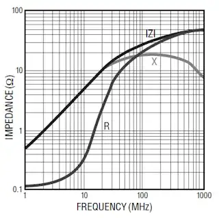
The impedance curve shows a 0.5 Ω/MHz slope, so at 100 Hz the reactive part of the inductance is negligible.

What is actually needed is suppression of low frequency noise, like 100 Hz ripple from the power supply. Then this inductor is pretty useless, and it's like just having the capacitor.

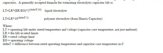
For low frequencies inductors can be impractically large, then a resistor instead of the inductor would have been a better choice. The datasheet says AVCC shouldn't be lower than VCC - 0.3 V, but I couldn't find how much current AVCC uses. That won't be much, say 10 µA maximum. The cutoff frequency of an RC filter is

\$ f_C = \dfrac{1}{2 \pi RC} \$

So if we use a 15.9 kΩ resistor with the 1 µF capacitor, we have a 10 Hz cutoff frequency, and the frequency response will look like this:

enter image description here or here

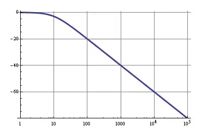
The 10µA through 15.9 kΩ is a 159 mV drop, so that's within spec. A 100 Hz ripple will be attenuated by 20 dB, that's 1:10, which isn't much, but VCC should have been decoupled properly already, so the 20 dB is just extra. Above 1 kHz noise will be reduced by at least 40 dB, that's a factor 1:100.

sitilge
  • 451
  • 2
  • 5
  • 15
stevenvh
  • 145,145
  • 21
  • 455
  • 667
  • Great answer Steven. Thanks a lot! (and thanks for the added picture in the question ;) – sarfata Jul 20 '12 at 18:11
  • @sarfata - my pleasure, thanks for the accept. But I didn't upload the picture, that was *jippie*. I removed your signature :-) (they're not allowed on the site) – stevenvh Jul 20 '12 at 18:15
  • Well thanks to you, I now know how to look at edit history ;) Thanks to everyone who cleaned up the question and made it better! – sarfata Jul 20 '12 at 22:18
  • 1
    IMPORTANT - READ THIS BEFORE USING A RESISTOR! I build a card with a Atmega 32U4 and the low-pass filter described on this page comments (15.8k resistor + 1 uF capacitor). It turns out that the current drawn on AVCC is much higher than expected: I measure 2.58V on AVCC with VCC at 3.30V (so I = (3.30-2.58)/15.8) = 45uA. The voltage drop is 0.72V, which is twice the allowed drop. The result is that the chip can not be programmed. You can read it but write fails all the time. I removed the resistor and connected AVCC directly to VCC and can now program the chip. [CC @stevenh] – sarfata Aug 10 '12 at 20:19
  • Also, in the datasheet, page 302, they describe the circuit used by Arduino and explain that they are trying to reduce EMI generated by the device. (fyi @stevenh) – sarfata Aug 10 '12 at 20:28
  • 1
    @sarfata - You still can use a resistor then, but have to use a lower value, like 4.7 k. – stevenvh Aug 10 '12 at 23:59
10

Some really good answers. My take is that the goal of the L-C filter isn't filtering out power supply ripple. That is best done with stiff (low ESR) caps on the power lines/planes and picking the right regulator part to start with. Plus, if you power your Arduino from a USB port the low frequency ripple sort of noise would be negligible.A cheapo wall wart is a switcher in the tens to hundreds of KHz range and will be electrically noisy but the voltage regulator and capacitance on the digital power rails should help there.

What the L-C L/P filter is doing is removing the sharp edges of the digital signals which find their way onto the digital power lines and if directly connected to the AVCC pins would find their way into the A/D conversion circuitry.

The reason the board wouldn't boot with the larger resistor (in the RC circuit) is that the PLL in the ATMega part is an analog circuit and uses the same AVCC pins as the A/D converters and it didn't get enough power. Maybe it really doesn't use both of the pins the same way in the part, but there's no differentiation in the data sheet (both are called AVCC). Layout-wise it's a pain to have pins 24 and 44 be the ones that go to AVCC since they are on opposite sides of the chip and who's going to bother to devote a whole power plan to them? You end up routing a signal across the part probably with vias on both sides, etc. Painful. The datasheet barely mentions this ugly bit of reality, almost like the extra pin was a second thought by ATMEL.

Anyway, these noisy signals come out of the Microprocessor itself when it switches internally and they don't hurt the digital logic, but trying to get to 10-bits of analog precision takes a bit more effort on the power supply side. Those digital noise edges are maybe in the tens of nS timeframe (100 Mhz-ish) so filters with this characteristic will work pretty well. If you work through the numbers, using AVCC=5V and 10-bits of A/D each LSB is about 5 mV. Seems like you'd need to have less than half that as a rough rule of thumb to have "low" noise.

The MH2029-300Y datasheet shows 20 Ohms at 100 Mhz. If the guy who tried the R-C filter had set the knee frequency at 1 Mhz it would have probably worked better because he could have picked a much smaller resistor. Something like a 22 Ohm resistor (to match the inductor's impedance at 100 Mhz) and a .01uF cap would have had a small enough DC voltage drop due to the input loading (45uA x 22 Ohm = 1 mV or so from his numbers). He'd be down 40 dB in the frequency of interest.

I wouldn't bet a layout pass on it but if the parts had the some footprint I might give it a shot (pick an 0805 footprint for both?) but with the inductor being a $0.10 part from Mouser, why not just stick with it?

DougG
  • 101
  • 1
  • 2
1

Yes, it's a low pass filter. The ferrite bead is a lossy inductive component that acts somewhat like a frequency dependent resistor, with L dominating at low frequencies and R dominating at high frequencies. The capacitor shunts higher frequencies to ground. Combined they form an LC filter with low Q, which does not experience the sharp resonant peak (as long as the cutoff is in the resistive region of the bead) that can cause problems in a "standard" LC filter.
However as Steven notes this part is not particularly suitable for this application, since it is a high frequency part and the ADC is relatively low frequency. It would be of use in something that requires filtering at much higher frequencies, like an FPGA design, high frequency ADC, etc.

Oli Glaser
  • 54,990
  • 3
  • 76
  • 147