37

I'm looking to drive a magnetic door lock from an Arduino. I've found a question about driving a solenoid from an Arduino, which includes a circuit that looks perfect for this kind of situtation:

Driving a device with a MOSFET

What I don't understand is how to select a MOSFET for the job. What properties should I look for, if I know my logic level, device voltage and device current?

In this case it's 5V logic, and the load runs at 12V / 500mA, but it'd be nice to know the general rule.

Polynomial
  • 10,562
  • 5
  • 47
  • 88

2 Answers2

40

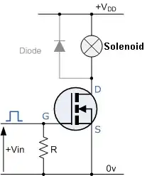
You've got a luxury problem: there are thousands of FETs suitable for your job.

1) the logic level. You have 5 V, and probably less than 200 mV or so when off. What you need is \$V_{GS(th)}\$, that's the gate's threshold voltage, at which the FET starts conducting. It's given for a specific current, which you want to keep an eye on too, because it may be different for different FETs. Useful for you could be maximum 3 V @ 250 µA, like for the FDC855N. At 200 mV (or lower) you'll have a leakage current much lower than that.

2) Maximum \$I_D\$ continuous. 6.1 A. OK.

3) the \$I_D / V_{DS}\$ graph:

enter image description here

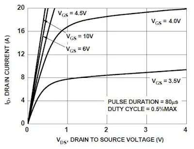
This one's again for the FDC855N. It shows the current the FET will sink at a given gate voltage. You can see that it's 8 A for a 3.5 V gate voltage, so that's OK for your application.

4) \$R_{DS(ON)}\$. The on-resistance determines the power dissipation. For the FDC855N it's maximum 36 mΩ at 4.5 V gate voltage, at 5 V it will be a little less. At 500 mA that will cause a 9 mW dissipation. That's more than good enough. You can find FETs with better figures, but there's really no need to pay the extra price for them.

5) \$V_{DS}\$. The maximum drain-source voltage. 30 V for the FDC855N, so for your 12 V application OK.

6) package. You may want a PTH package or SMT. The FDC885N comes in a very small SuperSOT-6 package, which is OK, given the low power dissipation.

So the FDC855N will do nicely. If you want you can have a look at Digikey's offering. They have excellent selection tools, and now you know the parameters to look out for.

stevenvh
  • 145,145
  • 21
  • 455
  • 667
  • Awesome, I'm pretty sure I get it now. I was looking at the [IRF520N](http://www.irf.com/product-info/datasheets/data/irf520npbf.pdf) from International Rectifier, which has a Vgs of 2.0V, but mentions a Vgs threshold max of 4.0V in the same table. What does that mean? It then shows a Vgs/Id graph with Vgs figures going as high as 10V. From the graph, it looks like the Id at Vgs=5V is more than high enough for my needs. I looked at the IRF520N because I can buy them locally for ~£0.21 each in TO220 cases. – Polynomial Jul 19 '12 at 10:23
  • 2 V is minimum 4 is maximum. That doesn't leave you much headroom, remember that's for only 250 uA, but then the graph shows *typically* 4.5 A at 5 V, so probably OK. I'd lean more towards the FDC855N, though, since that's maximum 3 VGS(th). – stevenvh Jul 19 '12 at 10:35
  • I'm having trouble sourcing the FDC855N, and I'd prefer through-hole cases. Is the [STP14NF12](http://www.st.com/internet/com/TECHNICAL_RESOURCES/TECHNICAL_LITERATURE/DATASHEET/CD00003059.pdf) a reasonable substitution? Vgs threshold is 2V min, 3V typ, 4V max @ Id=250uV. – Polynomial Jul 19 '12 at 10:47
  • @Polynomial - 15 A at 5 V looks good, the max 4 V Vgs(th) is the same as for the IRF520N. If you're happy with it, fine with me. – stevenvh Jul 19 '12 at 10:50
  • There's also the [STP55NF06](http://www.st.com/internet/com/TECHNICAL_RESOURCES/TECHNICAL_LITERATURE/DATASHEET/CD00002690.pdf), which has a Vgs(th) typ of 1.7V. Would that be going too far the other way? – Polynomial Jul 19 '12 at 10:53
  • @Polynomial - Don't think so. Minimum is 1 V, and I used 200 mV as an example for the logic 0 output, but that will probably be much lower still. Worst case you'll have say 10 uA leakage current, which for leakage is rather much, but it won't activate your lock, nor dissipate much power (1.5 mW). – stevenvh Jul 19 '12 at 10:58
  • 2
    Ah, I get it now -- the Vgs(th) min has to be higher than the logic leakage voltage, and the Vgs(th) max has to be lower than the normal logic high voltage. Excellent. I'll probably go for the STP55NF06 then, since it's cheap and locally sourceable. Thanks for all the help! :) – Polynomial Jul 19 '12 at 11:00
  • @Polynomial - Glad to be of help. Thanks for the accept. Success! – stevenvh Jul 19 '12 at 11:02
  • 1
    @stevenvh how do we consider the power dissipation when we select FET transistor (given the the question scenario)? – JeeShen Lee Jul 20 '12 at 01:59
  • 1
    @JeeShenLee - power = current x voltage = current squared x resistance. Also, voltage = current x resistance. Say you have a 2 A current, and you want the voltage drop to be 120 mV maximum, that's 1 % of a 12 V supply. Then resistance should be less than 120 mV/ 2 A = 60 m\$\Omega\$. You won't have trouble finding FETs which do even better. The power dissipation will then be 120 mV x 2 A = 240 mW, which even a FET in a small SMT package can handle. It's about choice. You can't do much about the current, but you can choose how much voltage drop or power dissipation you will allow. – stevenvh Jul 20 '12 at 05:01
  • This package is very tiny. :P – rozon Mar 19 '13 at 18:35
  • @rozon - No it isn't! :-) SOT-23 is a standard SMT package for low power transistors. Real small packages are leadless 0.8 mm x 0.8 mm. That's what I call small. – stevenvh Mar 26 '13 at 17:58
  • @stevenvh - I read the data sheet and something is not fully understood. I use Arduino, meaning I have 5v to operate. why on data sheet Vgs can be 10v or 5v ? – guyd May 23 '19 at 15:23
14

You need a MOSFET that will turn fully on with your 5V input, the spec to look for is Vth (threshold voltage)
Note that this figure is only the start of turn on, so the drain-source current will be very low still (often you see Vds = 1uA or similar as a noted condition)

So if your Vth is e.g. 2V, you probably want around 4V to turn it on well - the datasheet will have a Vg vs Id/Vds graph to show you how much the MOSFET will turn on with different gate voltages.
Rds is the drain source resistance, which can tell you how much power the MOSFET will dissipate (e.g. Id^2 * Rds)

Also you need it to be rated for the maximum drain source voltage and drain-source current (Vds and Id) which is in your case 500mA and 12V. So something like Vds >= 20V and Id >= 1A will be fine.

Oli Glaser
  • 54,990
  • 3
  • 76
  • 147