1

We were given the following question in our circuit theory class:

Find the relation between \$R,L,C\$ such that the net reactance across terminals \$A\$ and \$B\$ is \$R\$.

schematic

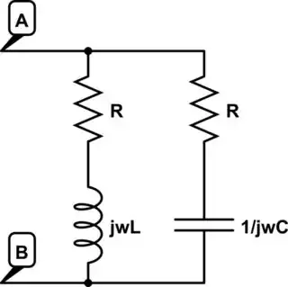
simulate this circuit – Schematic created using CircuitLab

I followed the generic method (equivalent parallel reactance):

$$\frac{1}{R}=\frac{1}{R+j\omega L} + \frac{1}{R+\frac{1}{j\omega C}}$$ to get the required relation (after eliminating \$\omega\$).

Upto that is okay. But I'm confused about something:

Suppose the system is inside a black box, with only terminals \$A\$ and \$B\$ outside. In that case how can we possibly distinguish between a black box containing this circuit vs. a black box which contains only a resistance \$R\$?

  • 1
    Well, what is the difference between reactance and resistance? What tools would you have in a lab that you could use to explore that? How can you measure just the resistive component? – John D Mar 08 '18 at 15:59
  • 1
    In which way did you eliminate \$\omega\$? – Arsenal Mar 08 '18 at 15:59
  • @Arsenal I found two equations by equating real parts and imaginary parts. Now, one variable \$\omega\$ can always be eliminated from two equations. –  Mar 08 '18 at 16:00
  • @JohnD Well, that exactly is my question. I don't know the answer. (I'm a beginner in this area...) –  Mar 08 '18 at 16:01
  • We don't just answer homework problems or assignments, you have to do some research yourself. So start off by figuring out what the difference between reactance and resistance is. A Google search will return lots of information. If you learn it yourself you're more likely to retain it and understand it. – John D Mar 08 '18 at 16:03
  • Will that elimination work for any frequency? – Arsenal Mar 08 '18 at 16:03
  • @Arsenal It should. \$\omega\$ is a variable –  Mar 08 '18 at 16:04
  • Set it to 0 then. – Arsenal Mar 08 '18 at 16:05
  • 1
    @Arsenal asks a good question, do you really believe that you can eliminate ω for all frequencies? – John D Mar 08 '18 at 16:06
  • 1
    @JohnD I don't think this qualifies directly as homework question as the question at hand came up during solving of an assignment and the answer to the assignment is not part of the question at all. – Arsenal Mar 08 '18 at 16:12
  • @Arsenal OK, maybe you're right. I had the impression that the black box question was part 2 of the assignment, but maybe not. Still, the OP should put in some effort to research the question and propose some methods. If he/she can't get there at all we can continue to give some hints :) – John D Mar 08 '18 at 16:16
  • @JohnD I'm getting confused now. When I put \$\omega=0\$, then \$\frac{1}{j\omega C}\$ is becoming undefined. So I don't think elimination will work(?) –  Mar 08 '18 at 16:16
  • For very high frequencies inductor can be replaced with an open circuit, while the other branch becomes purely resistive (\$R\$). For \$0\$ frequency. capacitor can be replaced with an open circuit, again while the other branch becomes purely resistive (\$R\$). Both for very high and 0 frequency we can't distinguish it from a pure resistance \$R\$. So how is this useful? –  Mar 08 '18 at 16:27
  • I would express the impedance between connections A and B using the fast analytical techniques. I can immediately state that \$Z(s)=R\frac{(1+s\frac{L}{R})(1+sRC)}{D(s)}\$ where \$D(s)\$ is the second order denominator made of two poles you'll need to determine. If the two poles are located at the zero positions, they cancel each other and \$R\$ remains. Develop \$D(s)\$ and look at the relationship between \$L\$, \$C\$ and \$R\$ for which \$D(s)=N(s)\$. Looks like the two time constants of this circuit must be equal to obtain this. Good luck! – Verbal Kint Mar 08 '18 at 16:30
  • @VerbalKint I can't really understand your method. Haven't learnt about poles, yet. Are you suggesting can we can distinguish using transient response? –  Mar 08 '18 at 16:33
  • Oops, if you know nothing about poles and zeros, I'm afraid I won't be able to help : { Look, you know that an inductor in dc conditions (for \$s=0\$) is a short circuit while a capacitor in dc is an infinite-valued resistance (open circuited). Redraw your circuit for \$s=0\$ with a shorted inductor and an open-circuited capacitor. You can see that the dc resistance (the leading term in my expression) is \$R\$. Now, you have to determine the values for \$C\$ and \$L\$ so that the rest of the expression is 1, in other words, the numerator equals the denominator. – Verbal Kint Mar 08 '18 at 16:39
  • @JohnD I forgot to ping you in my (second) last message. Any more hints from your side? –  Mar 08 '18 at 16:41
  • OK, you established the impedance at zero and infinite frequency. Now how about in between? Have you used a signal generator or a network analyzer? How would you measure impedance in the lab? – John D Mar 08 '18 at 16:51
  • Actually - my thinking went in the wrong direction. Sorry for that. I can't come up with a way to distinguish those two circuits... – Arsenal Mar 08 '18 at 16:54
  • Ok, what you need to do is develop and expand the impedance \$Z(s)\$ you wrote in your question. Then, factor \$R\$ as the leading term as I did. You should have \$R\$ as a leading term followed by a quotient. The numerator \$N(s)\$ will feature \$s\$ and \$s²\$ terms and the denominator \$D(s)\$ also. Simply write \$N(s)=D(s)\$ and solve for the value of \$L\$ or \$C\$ leading to this equality. I believe you should find \$\frac{L}{R}=RC\$. Next step is to quickly learn what poles and zeros are! : ) – Verbal Kint Mar 08 '18 at 17:35
  • Alright. I understood what poles and zeroes are (read it up). So, well, how does \$L/R=RC\$ help? @VerbalKint –  Mar 08 '18 at 17:39
  • If you don't develop the expressions as I recommended, you won't get there! If the quotient is 1 for all frequencies, then the leading term \$R\$ remains and the impedance is fixed. – Verbal Kint Mar 08 '18 at 17:40
  • @VerbalKint is helping you to get the correct values to solve the initial problem, but I don't believe it will help with distinguishing between the given circuit and a purely resistive one. – John D Mar 08 '18 at 17:47
  • 1
    The only way I can come up with to distinguish the two circuits is to apply a DC voltage to the terminals. This charges the cap if you wait a few time constants. Then immediately remove the DC voltage and measure the voltage at the terminals. If it's zero the circuit is purely resistive. If you see a voltage that decays with time there's a reactance present. – John D Mar 08 '18 at 17:50
  • @JohnD Hey! I think that's a good idea :) –  Mar 08 '18 at 17:55
  • 1
    @JohnD and Blue - my gut feel is that if you apply a dc voltage then take it away, the hold up from the cap will be exactly nulled by the back emf of the inductor so for ideal components you will still measure 0v between A and B rather than a decaying voltage. There will still be current flowing through the resistors though, perhaps you could use that (temperature? Thermal noise?). – Loganf Mar 08 '18 at 21:12
  • @Loganf Yeah, you are correct. The steady state inductor current under DC will be VDC/R, so it will cancel the voltage on the cap when the DC is removed. You could look for magnetic field outside the box. – John D Mar 08 '18 at 22:02

1 Answers1

-1

Connect a resistor between A and the output of a signal generator; other lead of signal generator to B. Connect channel 1 of your scope to the signal generator output and channel 2 of the scope to A. Sync the scope to channel 1. Vary the frequency and observe phase shift, and amplitude of A with respect to channel 1. If this doesn't make sense, I suggest you go read about LC resonance and Q. We can provide further assistance after you report your findings!

AlmostDone
  • 1,749
  • 7
  • 11
  • This doesn't work. We've already demonstrated that the reactances cancel out! – Dave Tweed Mar 08 '18 at 18:42
  • @Dave Tweed True...at resonance. But as you approach either side of resonance, XC and XL should be distinguishable. At some point >> resonance, C and R should prevail to yield a pole as evidenced by the 45 deg. shift and .707 drop in amplitude. – AlmostDone Mar 08 '18 at 18:49
  • Try it. **There is no resonance!** And besides, this was thoroughly hashed out a couple of years ago in the duplicate question linked at the top of this page. Even though the specific circuit is different, the same arguments apply. – Dave Tweed Mar 08 '18 at 18:55
  • The answer is have equal time constants, e.g. L = 220 uH, R = 100 ohms and C = 22 nF. If you ac-sweep this network impedance, the phase is 0° and the real part is 100 ohms. Follow the steps I gave in the comment section (factor R in the impedance expression and equalize N and D) and you're there in a few seconds. – Verbal Kint Mar 08 '18 at 19:37
  • @DaveTweed You are right, thanks for your comment. – AlmostDone Mar 09 '18 at 18:40