3

I have this three keypad connection sketches, all of which i've seen in various application, and some i've also used, but i want to know if there is any advantage of one over the other. enter image description here The keypad will be connected directly to DIO pins of a PIC microcontroller, PIN 1,2,3 as OUTPUTS, and PIN A,B,C,D as inputs.

The keypad will not be on board, but will be connected via cables to the PCB board, i don't know if this makes any difference.

TiOLUWA
  • 783
  • 1
  • 9
  • 23

3 Answers3

4

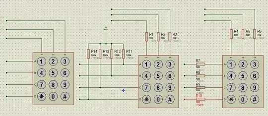
Number 1 can be destructive for your controller. If you would use push-pull outputs for the columns, and the rows as inputs, then pressing two keys on the same row will short circuit the power supply through the microcontroller's outputs. If the microcontroller's outputs can be configured as open-drain, then there's no problem, but the outputs must have pull-up resistors as well. Then you basically have number 2, but with the pull-ups integrated.

Number 2. Same story if you would use the rows as outputs. Using the columns as outputs makes more sense, since R1-R3 avoid a short-circuit of the outputs. Note that a low output level will see the series/pull-up resistor as a voltage divider, so that the input will be 0.1 Vcc, though that's usually not a problem.

Number 3 avoids the divider, but the resistors on the inputs don't serve any function. A variant without the series resistor will do.

So 1) may be an absolute no-no. 3) is a bit better than 2) because it doesn't have the voltage divider, but can do without the series resistor.
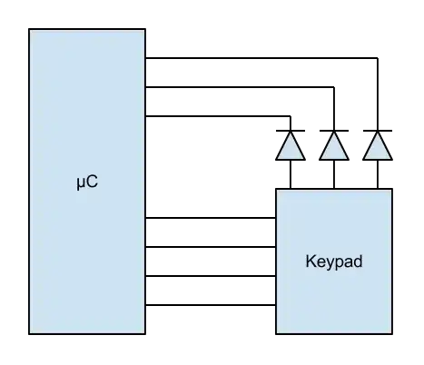
stevenvh
  • 145,145
  • 21
  • 455
  • 667
  • Thought I might as well delete mine, brain overtired... I read it as the columns are outputs, rows are inputs in the example though? – Oli Glaser Jul 18 '12 at 15:14
  • @Oli - In 1) it makes no difference, and there are no arrows, but I'll edit my answer to make it consistent with the others. – stevenvh Jul 18 '12 at 15:18
  • for 2) the pull-ups are on the rows, which will be inputs, so i guess that makes it ok right? but you say the series resistors on the columns are not necessary? and i didn't get your explanation on (3). are you saying the series resistors on the rows alone can be removed? becuase if all series resistors are removed, it becomes the same as (1) – TiOLUWA Jul 18 '12 at 15:33
  • 2
    @TiOLUWA - I didn't say the resistors of the outputs may be removed. They're required to avoid number one problems. But the series resistor for the inputs don't serve a purpose, since the inputs are high impedance. – stevenvh Jul 18 '12 at 15:36
2

You could just add diodes to the first schematic if your microcontroller has built-in pull-ups or pull-downs.

Keypad connection

The example shown assumes you have pull-ups on your inputs (to select a column you have to drive it low) and the state of the key is inverted.

If you have pull-downs on your inputs, you reverse the polarity of the diodes and to select a column you have to drive it high. You don't have to invert the value read.

Bruno Ferreira
  • 4,470
  • 2
  • 25
  • 36
1

The first schematic is fine assuming you are using a two phase scanning approach. In phase 1, the row GPIO pins are configured as inputs with internal pull-up resistors enabled, and the column GPIO pins are configured as outputs set to GND. In the second phase, the roles ae reversed. In each case, the 4-bit (or 3-bit) input read is stored away, and the "union" of the two phases gives an 8-bit (or 7-bit) value with you can decode into "button X was pressed." Of course, there are button combinations that are ambiguous to decode in this scheme (e.g. co-linear). You will also need to provide a small delay between changing the pin functions and reading the inputs so that the pins can charge up. That being said, it's a good minimal hardware approach, and as long as you obey the rules in software, there's no hazard to your controller.

vicatcu
  • 22,499
  • 13
  • 79
  • 155
  • I recognize that this scanning method is not what was proposed by the OP, but I wanted to explain the software context where the first schematic makes sense to use – vicatcu Jul 18 '12 at 16:34
  • i saw this scanning method used in one of microchips app notes using their port expander. Does it have any advantages over the regular method where you bring each COL low one after the other? – TiOLUWA Jul 19 '12 at 09:11
  • @TiOLUWA: are you perhaps alluding to Microchip ["AN1081: Interfacing a 4x4 Matrix Keypad with an 8-Bit GPIO Expander"](http://www.microchip.com/stellent/idcplg?IdcService=SS_GET_PAGE&nodeId=1824&appnote=en529784)? – davidcary Jun 06 '13 at 13:21
  • @TiOLUWA it's a two phase method so you can scan the matrix faster in principle I think – vicatcu Jun 07 '13 at 02:05