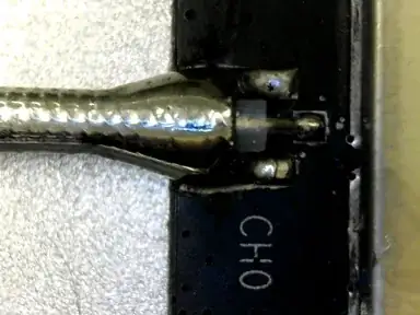
Is there an ideal method to solder a bare cable to a PCB for microwave (5-6GHz) signals?
The U.FL connectors that are normally used in this application are terrible, and there aren't many (or any) manufacturers making U.FL ends for this kind of cable anyway.
As far as I can tell, we're getting near-ideal data rates with the current methods. I'm a little concerned about reflections at the transition between PCB and cable, because I can't be sure the impedance is correct across the junction. Others have voiced concern about RF "leaking" at the joint - the center conductor is unshielded where it is soldered to the PCB.
I was able to increase the received power on the analyzer by making a minor modification in my soldering technique. I would interpret that as making an overall improvement - more of the power getting radiated, right?
I'm attempting to be sure our production techniques are giving us the best results I can, but after hours of searching I can't find anything much better than this - Can I solder a RG316 coax directly to a PCB instead of using the intended SMA connectors?.
EDIT: I've added a photo of the current "target" connection. The resist layer has been etched away at the 'neck' to provide greater structural support than bare PCB pads. The coaxial cable diameter is .080", for size reference.
