10

We are currently working on a bio medical project that is an ECG machine.There is a problem that we are unable to solve on software side is the removal of 50 Hz noise. Now we are trying to remove 50 Hz noise using analog filters. Does anybody have an idea of removing 50 Hz noise using analog components.

(the original title stated that the problem was in the signal — Steven)

Scott Seidman
  • 29,274
  • 4
  • 44
  • 109
Idrees
  • 101
  • 1
  • 1
  • 3
  • Where is the noise source? conducted or radiated? What are the test results? Noise on PS, Noise on CM, Noise on output for gain=? – Tony Stewart EE75 Jul 18 '12 at 12:32
  • Can you post the schematic of the power supply? – stevenvh Jul 18 '12 at 13:17
  • How about a photo of your setup? – Tony Stewart EE75 Jul 18 '12 at 13:18
  • @Idrees Why are you unable to remove the 50Hz noise in software? Nothing should be easier: masking the 50Hz peak in a fft and inverse transforming has always worked flawlessly for me. Generally the 50Hz noise produces an extremely sharp (single point) peak so that virtually no useful signal is lost. – ARF Jul 18 '12 at 19:50
  • @ARF And don't forget to remove 100 and 150Hz peaks, too) – yo' Dec 18 '14 at 19:28
  • Guys, what are possible "DC" levels, that may be found on common mode of the ECG electrodes? –  Aug 12 '15 at 17:34
  • Also remember if your device goes to USA or Japan it must have the notch filter tuned to 60Hz. – KalleMP Sep 30 '19 at 15:15
  • Don't forget us in Canada too. @KalleMP Would be pleasured to meet you. Drop by Toronto anytime. We have room. – Tony Stewart EE75 Sep 30 '19 at 16:50
  • Gareth You are missing something obvious but missing in your question. Coupling to ground , earth and mains. proximity of interference with complete air gap to grip – Tony Stewart EE75 Sep 30 '19 at 16:53

3 Answers3

13

(note: the question said the noise was in the signal. Seems to be the power supply; see my edit further down.)

A 50 or 60 Hz notch filter is typically done as a twin-T filter. A passive twin-T has a poor Q-factor however, meaning that neighboring frequencies also will be attenuated, which can cause the ECG profile to be distorted.

An active notch filter may look like this:

enter image description here

Don't forget to recalculate the resistor values for 50 Hz; R1 will be 11.8 MΩ. Any opamp will do. The difference with the passive filter is shown in this graph:

enter image description here

Maybe not so clear, but the active filter's graph is the vertical line at 60 Hz. Much better than the passive filter.

edit re your comment
If the 50 Hz is on the power supply like you say it needs decoupling. First the power supply itself. A good regulator won't have a 50 Hz ripple on its output, so maybe the smoothing capacitors on the inputs are too small. (On second thought that ripple should be 100 Hz. A defective diode in the rectifier bridge would explain both 50 Hz and a too high ripple.) If the input ripple is much too large it may go below the minimum input voltage of the regulator. Can you post a schematic of the power supply with component values? You can also place a 100 µF capacitor at the output.

Also use a 100 µF in parallel with a 1 µF on the power supply inputs of ICs. If they're low power you can place a 10 Ω to 100 Ω resistor in series with the supply line, before the capacitors. So the capacitors are directly to the IC's pins. Note that the resistors will cause a voltage drop on the 5 V, so only use the 100 Ω if the supply current is less than 1 mA. Up to 10 mA you can use the 10 Ω. Higher is better, you'll have to see what you can afford. 10 mA through a 10 Ω resistor will cause a 100 mV drop, that's 2 %, which is probably acceptable.

stevenvh
  • 145,145
  • 21
  • 455
  • 667
  • Thanks alot for your reply sir.our acquisition and processing boards work on 5v.At the moment there is no noise from the patient side.so what we want is to remove the 50hz noise from the 5v supply that we are using.If we implement the given circuit after 5v supply.Will it attenuate the 50hz noise? – Idrees Jul 18 '12 at 11:45
  • @user10929 - No, that's different. I'll update my answer. (And you don't have to call me sir, I'm Steven) – stevenvh Jul 18 '12 at 11:47
  • hmm CMRR is noise from signal , while PSRR also needs to be high ( ps rejection ratio > 120dB ) Also beware of measurement error from other sources of ingress such as scope probes. – Tony Stewart EE75 Jul 18 '12 at 12:25
  • @Tony - well the higher the better, of course. But if you have 5 mV ripple on your power supply a PSRR of 120 dB means 5 nV, and while nice, I don't think it's necessary. – stevenvh Jul 18 '12 at 12:29
  • but if you have 20V Common Mode noise on V+ vs V- and only 100 mV of ripple with galvanic response of 300mV DC and DC gain of 1000x what do you do? – Tony Stewart EE75 Jul 18 '12 at 12:37
  • @Tony - In theory correct, but let's keep it real, shall we? :-) – stevenvh Jul 18 '12 at 12:39
  • 20V common mode hum on V+V- is real from a lab supply and that is floating.. CMMR takes take of that... 300mV od DC is real from galvanic response,, if less and not saturating it can erode PSRR perhaps to 0dB such that 1mV ripple * 1000x gain becomes 1 v hum – Tony Stewart EE75 Jul 18 '12 at 12:41
  • This is a classic case of a poorly stated problem. User has no idea if the noise is conducted or radiated and has tried active filters and more notch filters mask the symptoms – Tony Stewart EE75 Jul 18 '12 at 12:45
  • @Tony - OP obviously isn't experienced in troubleshooting. He's focused on one solution for a problem, probably the wrong one, and forgets to give us the complete view. Both our answers are about noise on the signal, where in the end it appears to be in the power supply. Well, questions like this happen... :-) – stevenvh Jul 18 '12 at 12:50
  • I prefer to consider all the possibilities before locking into one solution.. AC DC CMRR PSRR.. vs a filter. I missed the ps noise info ? how much? – Tony Stewart EE75 Jul 18 '12 at 13:05
  • @Tony - I miss the schematic to start with! :-( – stevenvh Jul 18 '12 at 13:14
  • Note that a notch filter would remove a 50Hz pure sine wave. If there's any distortion in the offending signal, the distortion products will go through the filter untouched. – gbarry Jul 18 '12 at 13:53
  • @gbarry - Not quite. Any signal with a 50 Hz component in it will be affected. A 50 Hz harmonic is a sine, whatever the complete signal looks like. Only if no harmonics appear in the filter's bandwidth the signal can pass untouched. – stevenvh Jul 18 '12 at 13:58
  • For example a 50Hz triangle wave has odd harmonics same as a square wave except the harmonics are even 0,360deg instead of odd. (180deg) mr idrees needs help specifying the situation in more detail to load current, and source ripple. and what has ben tried. – Tony Stewart EE75 Jul 18 '12 at 21:19
  • Guys, what are possible "DC" levels, that may be found on common mode of the ECG electrodes? –  Aug 12 '15 at 17:34
  • is this op-amp single supply? – user16307 Dec 03 '15 at 10:58
10

As a student, we designed and tested our own discrete Instrument Amplifier (IA), using a standard 3x Op. Amp. for Biomedical Engineering lab experiments in 1974. We used it for ECG, EEG signal and prosthetic control. As well we applied electrodes to my temple and used it to monitor eye movement. It created a sawtooth with lateral eye movement, which grabbed the attention monitoring girls walking by and some stopped to volunteer for ECG tests. (with electrodes applied to chest) Once we understood the design requirements for CMRR, the 50/60Hz hum disappeared.

Here is my debug checklist for you;

  • Does your design meets the 120dB criteria recommended or just the minimum of 100dB?
  • Do you use a single Op Amp or the triple Op Amp design?
  • Can you try the floating back-drive method or "guarding technique" known in the medical industry for ECG as "right-leg-drive"
  • Do you have a high galvanic skin DC error response saturating your high gain amp or compromising the CMMR?
  • Can you provide some test measurements results?

When a 100V E-field ingress is superimposed on a 100uV signal and if you have a good common mode rejection ratio of 120 dB, you get a 100uV noise level.

Ways to Improve CMMR related 50/60 HZ hum are:

1. Use a high quality design Instrument Amp (IA) ( but very low cost)

2. Guard signal with “right leg drive” technique. (known as analog guarding method) where you buffer common mode signal to make a low impedance common mode reference on the leg that is still floating but suppresses the high E fields voltage of 50/60Hz by impedance ratio.

  1. Shield probe wires

  2. Use higher CMMR designed Instrument Amp >130dB

  3. Use an active tuneable Notch filter with Q=100 ( such as reported earlier )

  4. Use CM Ferrite choke around cables. ( high permeability type sleeve)

  5. Ensure V+ supply is noise free with Linear regulator, low ESR cap on in and output. and use short leads between V+ and amp.

My preferences in bold

enter image description here

Tony Stewart EE75
  • 1
  • 3
  • 54
  • 182
  • We are using ADS1298 Low-Power, 8-Channel, 24-Bit Analog Front-End for Biopotential Measurements.its CMRR is 115db.Do we need to increase the CMRR. – Idrees Jul 18 '12 at 12:10
  • @Idrees - I think Tony hasn't read the comment to my answer, that the problem is in the supply, not the signal. Could you add that information to your question, please? – stevenvh Jul 18 '12 at 12:14
  • I had assumed they used a linear supply.. hmmmmm – Tony Stewart EE75 Jul 18 '12 at 12:18
  • Currently we are using our machine on battery back up.We are taking the ECG of patients and the results are perfect.But when we use our machine on ac power.50 hz noise came into play.and it starts distorting the signal. – Idrees Jul 18 '12 at 12:20
  • @Idrees - Added this to my answer, about ripple from the smoothing capacitors: *On second thought that ripple should be 100 Hz. A defective diode in the rectifier bridge would explain both 50 Hz and a too high ripple.* – stevenvh Jul 18 '12 at 12:36
  • +1 just for the story. I'd give another +1 for the answer but the site doesn't allow it. – akohlsmith Jul 18 '12 at 14:02
  • 1
    Guys, what are possible "DC" levels, that may be found on common mode of the ECG electrodes? –  Aug 12 '15 at 17:35
9

Trying to filter out the 50 Hz noise should be the last resort only, in part because your valid signal frequency range includes 50 Hz. Anything you do to reduce 50 Hz will distort your desired signal too.

The best answer is to design the analog front end to minimize the line frequency pickup in the first place. The 50 Hz is coming from capacitive coupling of the power line, which is all around the room. However, you are measuring the difference between voltages at several electrodes on the body, and the 50 Hz power line hum will be largely a common mode signal.

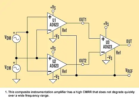
ECG front ends need to be extra squeaky clean about common mode elimination. This means full differential signal handling to well past 50 Hz, making sure each leg has the same impedance, using instrumentation amps with good common mode rejection, absolutely no ground reference for one side of the measurement, etc. The power line common mode noise can be many times the amplitude of the signals you are trying to pick up, so you really really have to wake up and pay attention to this issue.

Another thing most ECG systems do is to put a electrode on the leg opposite the heart, which is usually the right leg. This is used purely to pick up the common mode signal, amplified, and then it becomes sortof a floating ground reference for the first stage differential circuits until the differential signal can be amplified and its impedance lowered.

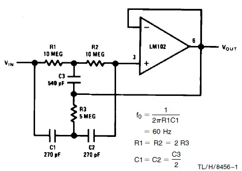
If you do all that right and you still have too much power line noise, then you can consider power line frequency reduction of the final signal. However, this is best done in software so that you can make the filter tight without running into analog component tolerances. That also allows you to measure the power line and make a filter synchronous to it. The resulting very tight notch will have less impact on the real signal than a analog filter with affordable parts. The analog filter has to be broader due to part tolerances alone to guarantee enough 50 Hz attenuation even if the center frequency is off a bit.

So in summary, in order of precedence you should attack the problem by

  1. Carefully design the analog front end for extra good common mode noise rejection.

  2. Carefully design the analog front end for extra good common mode noise rejection.

  3. Carefully design the analog front end for extra good common mode noise rejection.

  4. No, that's not good enough. Go back and fix your analog front end for better common mode noise rejection.

  5. Use a common mode pickup on the opposite leg to help cancel out common mode noise, then repeat from step 1.

  6. Eliminate the remaining power supply noise with a software filter synchronous to the power line.

Olin Lathrop
  • 310,974
  • 36
  • 428
  • 915
  • The noise isn't in the signal as the original title stated, but in the power supply. Yes, Tony and I also answered in relation with the signal. :-( In a comment to Tony's answer OP says it works fine on battery. – stevenvh Jul 18 '12 at 13:50
  • 1
    @stevenvh: Argh. It's annoying when people hide relevant information to the question in comments to specific answers instead of updating the question. I'll leave this answer here since it may show up in searches and be useful to other people designing ECG systems. – Olin Lathrop Jul 18 '12 at 13:57
  • Guys, what are possible "DC" levels, that may be found on common mode of the ECG electrodes? –  Aug 12 '15 at 17:35
  • Your answer is very helpful and I'm happy I found it. – not2qubit Mar 27 '19 at 13:55