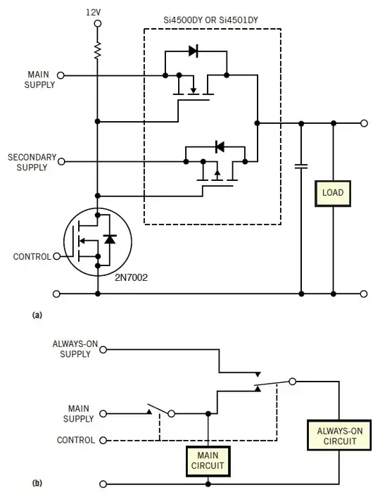
I'd like to breadboard a simple circuit which implements a mosfet pair to emulate a mechanical SPDT switch.
The circuit schematics can be found here.
The circuit looks identical to one that can also be found in page 8 of Vishay's Si4700DY Datasheet.
Assuming that both the Main Supply & the Secondary Supply are 12Vdc, and that the load doesn't exceed 0.3A, my first two questions are:
(1) What would be a suitable value & rating for the resistor in this circuit?
(2) Would it be ok to use a 12Vdc signal for the Control Signal of this circuit?
Moreover, the last answer to another, related question posted on this forum here, suggests an even simpler circuit to achieve the same goal as the present one (or so it seems to me).
My questions in this context are:
(3) Is the simpler circuit correct?
(4) Would it work in my case given the above specs?
Many thanks!
