21

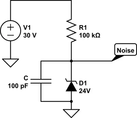
I have the following schematic of a Zener based noise source:-

schematic

simulate this circuit – Schematic created using CircuitLab

When built, an oscilloscope reveals a saw tooth noise signal at the "Noise" node, like:

Zener noise

The time base is 1us/div. Can anyone explain why the signal is saw tooth shaped? Initially I expected a triangular, or even sine shaped wave form. I think that it's something to do with the impedance of the Zener in conjunction with the much higher 100 kOhm resistor. The electrons cascade freely across the junction, but the resistor restricts current flow when the avalanche stops. We're talking 60uA. The result being slower charge build up than when current flows during avalanche.

This wave form isn't particular to my set up. There are other examples elsewhere on the Interweb when people have really zoomed in on the signal, one being https://youtu.be/CAas_kbTW3Q?t=714. Also there's a good chart here showing the rising edge to be slightly curved. It's probably unfamiliar as it's usually shown with a much slower time base. Am I right about the resistance/impedance explanation?

Paul Uszak
  • 7,327
  • 5
  • 37
  • 69
  • Is there a capacitor you aren't telling us about? Or, what is the junction capacitance of the diode? –  Mar 02 '18 at 13:54
  • @BrianDrummond Nope, just what's shown and a 50 Ohm lead direct to the scope. It was soldered bug style (clearly excluding the 30V psu). – Paul Uszak Mar 03 '18 at 23:50

2 Answers2

22

Consider that you effectively have this:

schematic

simulate this circuit – Schematic created using CircuitLab

where C is the junction capacitance, plus any external capacitance (leads, breadboard, etc). Some of the current from R1 leaks through D1, but the rest charges C. Once the voltage reaches a certain level, avalanche breakdown occurs and current flows from C until the avalanche stops. Then the current begins charging C again.

To calculate C you first need to know the leakage. Decrease V1 until the noise disappears. Then measure the current. Then increase V1 back to 30V. Measure the rising slope of the noise dV/dt. Measure the average value of V. The current through R1 is approximately constant at (30V - V)/100kohm. Subtract the leakage current from this, then use I=C dV/dt to calculate the capacitance.

τεκ
  • 4,229
  • 1
  • 16
  • 17
  • How did you arrive at the 10pF value please? And do you see breakdown as effectively being a short then across the Zener? – Paul Uszak Mar 02 '18 at 12:35
  • @PaulUszak I've added a bit on how to calculate the capacitance (which also includes the breadboard capacitance, if you're building this on a breadboard). Typical values for the junction capacitance of zener diodes seem to be in the range 10-100pF. Look at the graph on page 6 of [this datasheet](http://www.onsemi.com/pub/Collateral/BZX84C2V4LT1-D.PDF). They also do make low-capacitance zener diodes. – τεκ Mar 02 '18 at 15:55
  • @PaulUszak When breakdown occurs it's the zener impedance (70 ohms-ish). If you zoomed in enough you could probably estimate that from the slope too, especially if you added more capacitance to slow it down. – τεκ Mar 02 '18 at 15:59
  • Could this setup be used in a comparator for a PWM controller designed for a DC-DC converter, just as a hobby project? – Daniel Tork Mar 02 '18 at 19:35
  • @DanielTork to get a random pulse time? – τεκ Mar 02 '18 at 20:00
  • @τεκ You mean I won't be able to calculate the pulse time? Isn't there a way to get around this problem? – Daniel Tork Mar 02 '18 at 20:04
  • @DanielTork It is literally random. Commonly used in hardware random number generators. Look at the question. – τεκ Mar 02 '18 at 21:13
  • @DanielTork The waveform (other than being sawtooth) is entirely random under the control of the Heisenberg Uncertainty Principle. God himself cannot determine the size of the next tooth. I use it for true random number generation. It would be less than useless in a DC-DC thingie. – Paul Uszak Mar 03 '18 at 00:03
6

The random discharges near breakdown are from random crystal dielectric charges breaking down under a high E field producing a pulse current that drops the voltage with an RC fall time. If you could measure how small the fall time was , you could estimate the size of the C in that charged particle.

If I guess each particle sees at least 50kV/mm or 50V/um or 50mV/nm so the charge size may be about 10 to 20 nm to get 500 to 1000 mV. This can be scaled according to the epixtaxial particle sizes in the Si crystal lattice.

Like a Unijunction oscillator except with random thresholds in a limited range, the C charges up and the Zener voltage collapses rapidly 1~5% just below the breakdown threshold at very low currents.

From looking at the waveform I expect the rise/fall time ratio to be ~ 100 or less in this sawtooth.

Tony Stewart EE75
  • 1
  • 3
  • 54
  • 182