2

Im new to use of mosfets.

If I was to use two Mosfets with an Arduino, would I be able to drive them both with just one digital pin connected to both mosfet's gates but opposite actions?

For example: Digital pin 2 goes High, Mosfet-1 opens a circuit, Mosfet-2 closes a circuit... and vice versa.

I'm currently using n-channel mosfets but I read about p-channel. Having p & n gates tied to one pin?

sryan2580
  • 117
  • 9
  • I can add a schematic later. I'm making a battery drainer/charger for capacity calculations. The mosfets are for turning on and off the charging and draining circuits. As soon the batteries fully charge, draining occurs, once complete charges again. Ive run out of pins on my Nano as i now have 8 n-channel mosfets controlled by 8 pins. (system has 4 cells in individual circuits hence the number of mosfets) – sryan2580 Feb 19 '18 at 12:23
  • Please tell more about the voltages you use, also are the FETs high side or low side switches? – bobflux Feb 19 '18 at 12:59
  • A drain circuit is liion voltage @ 1A. A charge circuit is 5v @ 2A. The N-Channels im using are IRF3205 and the P-Channels are IRF4905 – sryan2580 Feb 19 '18 at 18:04

3 Answers3

2

The answer to your question is, yes sometimes.

Provided the P-Channel device is connected to the same rail as the MCU, you can use a circuit like below quite happily.

schematic

simulate this circuit – Schematic created using CircuitLab

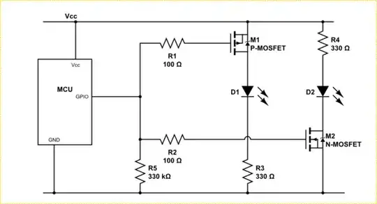
This circuit turns on either LED depending on the state of the GPIO pin. When LOW M1 will be on and D1 will be lit. When high, M2 will be on and D2 will light.

You do however need to be aware that you are doubling the gate capacitance being driven by the MCU pin and as such turn on and turn off times will be extended in this configuration. The double cap also increases the required gate switching current.

Note each MOSFET should have it's own gate resistor, R1 and R2 here, and those should be sized so the switching current of both added together does not exceed the drive current of the GPIO.

The "default condition resistor", R5, can be a pull down as shown, or a pull up, depending on which LED you want to be on when the MCU is not initialized yet.

Both the P and N MOSFETS need to be chosen to have a maximum Vgs-Threshold around Vcc/2.

NOTE: The MOSFETS will not switch at exactly the same time. As such you should not depend on this circuit to drive a push-pull type load or other circuit that depends on edge coincidence.


If the P-Channel is attached to some higher rail, then you need something more complicated, like Wesley's answer.

Trevor_G
  • 46,364
  • 8
  • 68
  • 151
0

As far as I understood from your question, you want to set 1 mosfet on and the other one off with single pin. What you are looking for is exactly what you have suggested. Using n and p channel mosfets.

https://en.wikichip.org/wiki/File:MOSFET_flow.svg

  • Wow, I didn't trust my own research. Thanks for your help! – sryan2580 Feb 19 '18 at 12:27
  • In practice it is far, far more complicated than that. What many do not realize is that (in crude terms) PFETs cannot be directly applied unless the MCU I/O voltage supply matches the load voltage to be switched by the PFET. Also selecting suitable FETs for drive by low voltage MCUs is non-trivial, especially if one is unwilling to use surface mount devices. – Chris Stratton Feb 19 '18 at 17:59
0

If you want to do it using only N-FETs:

schematic

simulate this circuit – Schematic created using CircuitLab

When the digital signal is high:

  • M3 is on.
  • M1 is on, pulling the gate of M2, keeping it off.

When the digital signal is low:

  • M3 is off.
  • M1 is off, Rpullup turns M2 on.
Wesley Lee
  • 7,844
  • 6
  • 35
  • 53