0

In my current project, I try to connect a load rated at 5V/2A with a 5V power supply. To avoid plugging and unplugging the supply over and over again, I decided to add a push button. To turn the device on and off, it must be held down for 3 seconds. Constructing this circuit is harder than I thought it would be.

Circuit

(This is just the beginning.)

When the button is pressed, C2 charges through R1. After some time, Q1 becomes saturated when C2's voltage drop gets higher than 0.7V. Load resistor R2 is powered at this time. However, this circuit is missing crucial aspects: The current through the load equals ~2A, there should be no voltage drop bigger than 0.01V across the transistor when saturated, C2 must discharge way faster to timeout a press shorter than 3 seconds, and most importantly, R2 must keep its voltage.

My suggestions would be:

  • Instead of feeding the voltage across C2 directly through the base-emitter junction, I could compare the voltage with a comparator, then feed the output (HIGH / LOW) to a power MOSFET
  • Use some kind of latching circuit or flip-flop to keep the voltage at R2 consistent
  • Add a resistor parallel to C2 with an N-channel BJT to open a discharge path when SW1 is open (inverter?)

Will this approach work? Or is there an even simpler solution?

EDIT

To clarify why I can't use switches, here are some reasons:

  1. The switch is exposed to the outside. If the user accidently hits it, it cuts the power, therefore losing all unsaved data without any warning. Even with a timer, most of the time the user wouldn't realize it fast enough.
  2. The push button is used to give a smartphone-like interface. It can trigger different things after a certain time held down instead of a switch with only 2 states.
Overblade
  • 217
  • 4
  • 9
  • 1
    If this is a one time application, I would use an NE555. Seems faster and simpler than doing with discrete parts. – lakeweb Feb 18 '18 at 20:17
  • I heard it can only sink or source 200 mA at its output, so I'd need a MOSFET, right? – Overblade Feb 18 '18 at 20:18
  • Yes, you would still need an output stage. BJT would work also. I was thinking about the timing challenge. – lakeweb Feb 18 '18 at 20:20
  • It sounds clear to me, but I want to ask in my own words to be sure. You ***want*** it to take 3 seconds of the push button being held down in order to turn the power on ***and also*** you ***want*** it to take a different 3 seconds of applying the push button the same way in order to turn the power off? – jonk Feb 18 '18 at 20:45
  • Exactly. It's like the power button on smartphones: 3 seconds to turn on, and on older ones another few seconds to turn off. – Overblade Feb 18 '18 at 20:47
  • You also do not want to use an MCU. This is supposed to do all this entirely in analog. Yes? – jonk Feb 18 '18 at 20:49
  • I'd prefer a circuit with small IC's and discrete stuff as the load is already an MCU. – Overblade Feb 18 '18 at 20:53
  • So something bullet-proof in the sense that it cannot be disabled by software that has crashed. And this shouldn't be an external watchdog IC, either. Since it is possible that your software might be crashed, but in a loop feeding the watchdog. So all those ideas are eliminated, correct? (It still seems to me that a working bit of software in a separate 50 cent MCU would be bullet-proof. But I must ask.) – jonk Feb 18 '18 at 20:55
  • Yes, exactly. It's isolated from the MCU's software level. – Overblade Feb 18 '18 at 20:58
  • Then one more question, just to make absolutely sure. Why not use a cheap, external SOT-23-6 MCU which has been strictly and solely programmed for this function? First off, such code is easy to write and nearly bullet-proof on its own. Second off, the chances of both your MCU code going awry AND ALSO this new SOT-23-6 MCU *also* having a bug making it fail too is rather unlikely. Why is that not an acceptable solution here? – jonk Feb 18 '18 at 21:03
  • I don't have any experience with programming MCU's on its lowest level. My load MCU already has circuitry to do that. If a solution with an external MCU is simple, effective and easy to set up, I'll definitely give it a try. – Overblade Feb 18 '18 at 21:09
  • Comparator, RC, D flip-flop, P-channel mosfet. Something like that. – user57037 Feb 18 '18 at 21:43
  • @Overblade: Note that when you use the schematic button on the editor toolbar that your editable schematics are saved inline in your post. This makes it easy for someone to copy and edit the schematic in an answer. It also avoids the grid in the background. No need for screengrabs. – Transistor Feb 18 '18 at 21:46
  • @Transistor oh ok thank you, I'll remember it next time – Overblade Feb 18 '18 at 21:47
  • 1
    My suggestion is to just use a simple mechanical toggle switch. – user57037 Feb 18 '18 at 23:30
  • The way this normally works in real products is that the switch would be an input to the processor that is in control, and the processor would initiate an orderly shutdown after the switch is held down. Sometimes some type of external watchdog timer also monitors the switch. The watchdog timer is capable of doing a hard power cycle in the event that the firmware does not respond. It is rather complex, as you are figuring out. And it is normally designed into the product from the start. – user57037 Feb 19 '18 at 16:57
  • I agree, but my problem is I have no direct control over the processor. I can only connect/disconnect power and I/O via hardware pins. – Overblade Feb 19 '18 at 16:59
  • Can you control code on the processor? Does it have IO pins that you can use as outputs? – user57037 Feb 19 '18 at 17:02
  • I can only indirectly control code on the processor. There is an OS between software and hardware, so direct control is impossible. – Overblade Feb 19 '18 at 17:10
  • Well, can you read IO pins? And can you set other IO pins into specific states? If so, you can do all the logic in code. – user57037 Feb 19 '18 at 20:30
  • Yes, I can. But how should it power itself via pins? – Overblade Feb 19 '18 at 20:35
  • I am not sure I am up to explaining it all. I will try to write an answer later. – user57037 Feb 19 '18 at 22:24

4 Answers4

3

Let me show you the problems with your question. There are several unanswered questions that arrive from a simple state machine table. (The following assumes a debounced PB.)

  1. OFF STATE: On entry to this state, turn off the power to the MCU. If the PB is unpressed, continue in this state. If the PB is pressed, then start a 3-second timer and go to step 2. (Regardless of its prior state, it must be reset so that 3 seconds will elapse -- so this means that if there is a hardware timer and if for some reason that hardware timer is still timing away, you MUST be able to reset it the moment the PB is pressed.)
  2. TIMER PENDING: If the timer is still busy and the PB is still pressed, then continue in this state. If the PB is released, go to step 1. If the PB is still held, but the timer expires, then go to step 3.
  3. PB PENDING: If the PB is still held but the timer is on for some reason, there is an error in the timer -- go to step 2 and re-await the timer (or else choose some other behavior.) If the PB is not held but the timer is on, then there is an error in the timer -- go to step 1 and re-await the PB to restart the process (or else choose some other behavior.) Otherwise if the PB is still held, continue in this state. And if the PB is released, then go to step 4.
  4. ON STATE: On entry to this state, turn on the power to the MCU. If the PB is unpressed, continue in this state. If the PB is pressed, then start a 3-second timer and go to step 5. (Regardless of its prior state, it must be reset so that 3 seconds will elapse -- so this means that if there is a hardware timer and if for some reason that hardware timer is still timing away, you MUST be able to reset it the moment the PB is pressed.)
  5. TIMER PENDING: If the timer is still busy and the PB is still pressed, then continue in this state. If the PB is released, go to step 4. If the PB is still held, but the timer expires, then go to step 6.
  6. PB PENDING: If the PB is still held but the timer is on for some reason, there is an error in the timer -- go to step 5 and re-await the timer (or else choose some other behavior.) If the PB is not held but the timer is on, then there is an error in the timer -- go to step 4 and re-await the PB to restart the process (or else choose some other behavior.) Otherwise if the PB is still held, continue in this state. And if the PB is released, then go to step 1.

This is not so complicated for a PIC10F200. In fact, it's relatively trivial to perform. (It still will require an external driver circuit to handle the required current, obviously.)

However, this is quite a bit more complex to do in analog hardware. There exist components such as the 74121 that can be used to represent your 3-second timing component(s). You will also need something to keep track of the power-on state (some form of FF.) And also something to keep track of the current state and some added logic to make the state transitions.

That said, you might make some "don't care" decisions to help simplify the hardware logic involved. But you haven't specified what to do in the error conditions mentioned above (and you must decide what you can accept in those cases, because they might occur.)


An MCU requires a toolchain, learning curve, and some coding. That's a process by itself and I don't want to tell you that this is the better way. That's something you have to decide.

But I can say that the hardware logic won't be trivial, either. I see analog debouncing, a short term reliable delay as well as a 3-second delay timer (or two), one or more FF, and a variety of logic gates. And you would need to carefully specify all of the details. Look over the above logic and tell me exactly how you'd want to carefully describe the exact behaviors of this circuit.

I'd go with the SOT-23-6 MCU.

jonk
  • 77,059
  • 6
  • 73
  • 185
  • Good points you mentioned, I didn't think of those situations. – Overblade Feb 18 '18 at 21:52
  • Power on: MCU is off, PB gets pressed: 3s timet starts. When PB gets released before timer expires, the timer gets reset. If it's held for longer than 3 seconds, it will still turn on. When the PB gets finally released, functionality switches: The next time the PB is pressed and the timer expired, the MCU will shut down even if the PB is longer held. Functionality switches back to its original state. – Overblade Feb 18 '18 at 21:59
  • I think the MCU option offers the advantage of low current draw vs. flexibility. The circuit I just finished to 70% needs many logic gates and FFs (like you've already said). And these ICs have a current consumption of nearly 1mA when in idle mode. In comparison to a watchdog MCU with 1uA I see great potential in going with your solution. – Overblade Feb 20 '18 at 19:02
  • @Overblade You need to consider what toolchains you are already familiar with, then. I am fully set up for Microchip and TI and Atmel and ARM. But you may be set up for less. Of those, only Microchip (so far as I'm aware) offers a SOT-23-6 MCU -- the PIC10F2xx line. I'd probably go that way because they are small and cheap and once you've got these programmed up, you have a universally useful device that you may use elsewhere. And perhaps even sell to others. – jonk Feb 20 '18 at 21:43
3

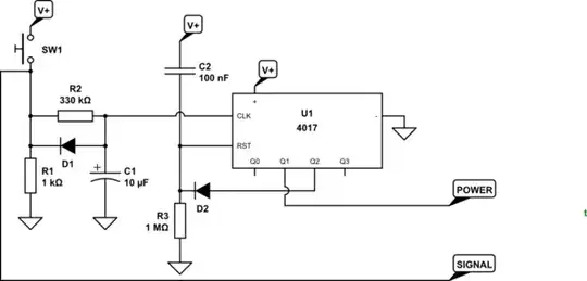
schematic

simulate this circuit – Schematic created using CircuitLab

Figure 1. A 4017 flip-flop.

How it works:

  • On power-up C2 pulls the RST pin high as the voltage rises. R3 discharges it. Q0 is on and Q1 is off. CLK input is low.
  • If SW1 is held for 3 s C1 will charge to the trigger level for the clock input. Q0 will turn off and Q1 turn on. Holding the button for longer will have no effect.
  • On releasing the button C1 will rapidly discharge through D1 and R1.
  • Pressing SW1 again for 3 s will advance the counter again, Q2 will turn on but since this is connected to the RST pin the chip will return to its initial state. D2 prevents Q2 interfering with the power-up reset pulse.

This sorts out the logic. I think you can figure out the power switching.

Power-down warning

With the addition of the signal line to your micro-controller you have a 3 s warning to trigger a "save data" routine before the power is cut. Some logic may be required in the controller to suppress this during power-up, etc.

Transistor
  • 168,990
  • 12
  • 186
  • 385
2

Will this approach work? Or is there an even simpler solution?

Use a toggle switch rated for 2A and at least 5VDC.

There doesn't seem to be any compelling reason to make this electronic.

user57037
  • 28,915
  • 1
  • 28
  • 81
  • I would do that, but the load's memory may get corrupted when the toggle switch is actuated. A push button with a timer is safer to prevent such accidents. – Overblade Feb 19 '18 at 05:18
  • I don't think the load will be able to tell the difference. – user57037 Feb 19 '18 at 07:36
  • It won't, but the user will if data gets corrupted. – Overblade Feb 19 '18 at 12:15
  • Why would switching the power using a toggle switch be more likely to cause data corruption than switching the power using a transistor? In both cases the power is cut suddenly with no warning to the load. – user57037 Feb 19 '18 at 16:36
0

there should be no voltage drop bigger than 0.01V

This is a problem for any solid state switch. The only approach that would satisfy this requirement would be a relay - reed or otherwise.

The relay itself could be activated from a T (or D) flip-flop circuit. That way the pushbutton would be sufficient to turn on or off the current through the load.

schematic

simulate this circuit – Schematic created using CircuitLab