11

I want to build a digital dimmer for resistive Loads. I have found this circuit for that:

dimmer

  • The input voltage is 220VAC 50Hz.
  • The red box in the picture is for Zero Crossing Detection.

When the AC voltage crosses the zero, the Microcontroller will be interrupted an therefore detects the zero crossing. so you can reach to the required voltage by triggering the Triac after a specific Delay.Do you recommend this circuit? if so, please let me know if there is any IC to replace with the Red Box (shown in the picture) to detect the zero points of AC voltage (as my circuit should be as small as possible)?

P.S. As I need this circuit to reduce the consumed energy of Loads, the circuit itself must dissipate at most 5 watts.

stevenvh
  • 145,145
  • 21
  • 455
  • 667
Mehrdad Kamelzadeh
  • 959
  • 4
  • 11
  • 22

4 Answers4

14

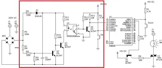
In the answers to this question is explained how you can do that complete zero-crossing detection circuit with just U1, R12 and 2 series resistors on the 220 V side. One solution uses a common optocoupler, the other one a Darlington optocoupler, which needs less current to drive the optocoupler's LED, so that's less power in the series resistors (less than 200 mW for the complete zero-crossing detector).

enter image description here

This replaces the red box plus the rectifier at the left.

edit dd. 2012-07-14
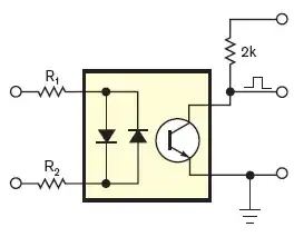
If an AC input optocoupler is too expensive, then you can use a common optocoupler with a 1N4148 in anti-parallel:

optocoupler

You'll have the advantage of lower cost and wider offering. The LTV-817 costs only 10 cent in 1000 quantity, yet has a respectable 50 % CTR. For only 2 cent more you get the LTV-815, which has a Darlington output. Instead of 1 positive pulse every half period you'll have a positive pulse a bit longer than half a period.

enter image description here

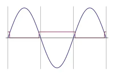
If the mains frequency is 50 Hz then one period is 20 ms. If then the positive pulse is 12 ms long you know that it covers two zero-crossings symmetrically. Since the zero-crossings are 10 ms apart there was one 1 ms after the start of the 12 ms pulse, and one 1 ms before the end. So you know that the next zero-crossing will be 9 ms after the end of the pulse.
This is very easy in software and keeps BOM cost low.
(end of edit)

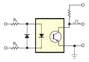
But watch out with the triac driver. The input is isolated from the mains through the optocoupler, but apparently they forgot that on the driver side, so the circuit is directly connected to the mains after all, and therefore possibly lethal!

You need an optocoupler on that side as well. Typical application from the MOC3051 datasheet:

enter image description here

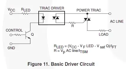
Make sure to use a random phase optocoupler (like the MOC3051).

stevenvh
  • 145,145
  • 21
  • 455
  • 667
  • [This other answer](http://electronics.stackexchange.com/questions/17008/how-can-i-detect-a-power-outage-with-a-microcontroller/17010#17010) of yours also explains it very well. – m.Alin Jul 13 '12 at 15:23
  • Of course. I was just pointing to an _additional_ source of information. – m.Alin Jul 13 '12 at 15:29
  • Steven I am really sorry but I am not very professional. will you help me figure this out?? where shall I put my Microcontroller? and as you said the first Image can be replaced by the Red Box plus rectifier. So can I connect the R1 and R2 directly to the 220VAC???? If yes what should be the Values of R1 and R2?? I am confused. :( – Mehrdad Kamelzadeh Jul 13 '12 at 16:48
  • @Mehrdad - Yes, R1 and R2 go directly to the 220 V. The calculation is somewhat involved, and depends on the type of optocoupler you choose. [This question](http://electronics.stackexchange.com/questions/33042/how-do-i-select-the-accompanying-components-for-an-optocoupler/33043#33043) explains the calculation in complete detail. Read it, twice if necessary. The 2k pull-up resistor goes to +5V, it agrees with your R12 (value: again, see calculation). The pin indicated by the pulse goes to PD2INT0, the bottom pin is ground. – stevenvh Jul 13 '12 at 16:57
  • @stevenvh the SFH620A you suggested was exactly what I wanted. But the price of that is expensive in my country as I want that for mass production. So I used the `Zero Crossing Detector` circuit which Bruno has sent here. Now to make everything clear for myself and to see that I have gotten everything right, I redraw the circuit and combined them. Just tell me your recommendations and if I have made mistake in that or it's just fine. I did that according to your post and the datasheets. http://www.imagetoo.com/images/toshow.jpg – Mehrdad Kamelzadeh Jul 14 '12 at 07:55
  • 1
    @Mehrdad - For mass production you'll want as few components as possible. Instead of needing several components to provide the perfect signal I rely on software to detect the actual zero-crossing in the middle of the pulse. For mass production software is virtually free. If the SFH620A is too expensive there are alternatives. Digikey lists 650 AC input optocouplers. The EL814 costs only half the price of the SFH620A. – stevenvh Jul 14 '12 at 10:02
  • @Mehrdad - If you can't find a cheap AC optocoupler locally you can also use a common one, and either use a 1N4148 in antiparallel with the LED, or use a bridge rectifier with 4 x 1N4004. 1st solution is cheapest, and will give you a pulse just a bit shorter than half a period. Again use software to determine the exact zero-crossing. This is the cheapest solution. If you're interested in it, but need help, ask a new question about it and I'll explain in detail. – stevenvh Jul 14 '12 at 10:07
  • @stevenvh I didn't understand what you mean by software? do you mean a simulation software?? will you provide me the circuit that the practice for what I want to do please? – Mehrdad Kamelzadeh Jul 14 '12 at 10:57
  • @Mehrdad - The microcontroller software. At the zero-crossing you'll have a pulse of, say, 1 ms long. Then the software will detect the first edge at time T, the second at time T+1 ms, and for a 50 Hz input it can predict the next zero-crossing: (T + T+1 ms)/2 + 10 ms. [Circuit](http://i.stack.imgur.com/BartJ.png): same as in my answer but with 1 diode external. Allows you to use a cheaper optocoupler. I'll add it to my answer. – stevenvh Jul 14 '12 at 11:22
  • @stevenvh I don't understand that if I could detect `Zero` why shall I predict that and calculate the next `Zeros`?? – Mehrdad Kamelzadeh Jul 14 '12 at 13:43
  • 1
    @Mehrdad - the actual zero-crossing is in the middle of a pulse, so you can only determine it after the pulse. If you wanted to fire the triac exactly at the zero-crossing you're a ms or so too late. So you set a timer for when the next zero-crossing is expected, and when that timer gives you an interrupt you know that's a zero-crossing. At the same time you're processing the input pulse to define the moment of the next zero-crossing. So you always use the input pulses for the next zero-crossing. – stevenvh Jul 14 '12 at 13:55
  • @stevenvh Oh now I understand what you are saying. and just one more question. what is RET in figure 11 (Basic driver circuit) is that the Ground of the DC voltage?? – Mehrdad Kamelzadeh Jul 14 '12 at 14:19
  • Thank You man! I just forgot to ask that did I calculate the Values of Resistors in this link imagetoo.com/images/toshow.jpg ? (I will use MOC3051) – Mehrdad Kamelzadeh Jul 14 '12 at 15:22
  • @Mehrdad - Rled < (5V - 1.5V)/20mA = 175 ohm. So 150 ohm is OK. Rtriac = 390 ohm (MOC3051 datasheet says current must be < 1A at peak voltage). And you forgot the base resistor for the 2N3904: 1k will give you 4 mA base current, more than enough to get 20 mA for the LED. – stevenvh Jul 14 '12 at 15:42
4

I'm not aware of any IC that can replace a full zero-cross-detector, but I have been using this circuit and it works quite well and it has a very low power consumption.

Zero cross detector

You can find more information here.

Bruno Ferreira
  • 4,470
  • 2
  • 25
  • 36
  • I have to use Microcontroller. Where should it be in this circuit? – Mehrdad Kamelzadeh Jul 13 '12 at 19:32
  • You should connect the signal marked as OUT to your interrupt pin. – Bruno Ferreira Jul 13 '12 at 19:34
  • Do you agree with the Load part of my circuit? have you got any suggestion or recommendation or it's just fine? – Mehrdad Kamelzadeh Jul 13 '12 at 19:41
  • For the load I would follow stevenvh advice. If you want isolation from mains for zero cross detection, you should also isolate the load control. Depending on the output current of your microcontroller and the characteristics of the opto-triac you use you may not nedd the transistor to drive the opto-triac. – Bruno Ferreira Jul 13 '12 at 19:46
2

This application note (AVR182: Zero Cross Detector) from Atmel describes how you can do zero-crossing detection with two 1M&ohm; resistors. This involved connecting the mains signal directly to the MCU which may or may not be a good idea, but it is very efficient in terms of components. If you're only going to drive the TRIAC it might not be a bad idea.

Just remember to insulate stuff when if you're debugging etc.

Edit: Updating URL to relocated application note.

Trygve Laugstøl
  • 1,410
  • 2
  • 19
  • 28
0

These are fine examples of nice working single/multichannel zero cross dimmers with IR/UART/DMX512.

avra
  • 1,872
  • 3
  • 14
  • 21