1

NOTE: Question was edited following comments and answers.

As you would probably all agree, current is in practice measured by putting a resistor of small resistance in series and then measure voltage across that resistor. (I know there are other scientific methods, but are they used in everyday hobby applications?)

Measuring voltage precisely is no problem. A cheap four channel AD converter (combined with a microcontroller or i2c to USB controller) accuracy might be upwards of 1% quite easily according to Andy aka (IMHO upwards of 0.5%).

However, what I find problematic is that resistors of small resistance and small tolerance are very difficult to obtain or cost forbidding prices. Four power resistors of 1 Ohm and only 5% tolerance are twice as expensive and at least an order of magnitude less accurate. Only one low power 1 Ohm resistor with 0.1% tolerance cost several times ADC price.

What is the possible solution to that problem? One idea is buying a cheap power resistor and determine its true resistance and correct the result, but how to determine its true resistance? Naturally, measuring small resistances is just as difficult as measuring small currents.

Are there any simple hobbyist method to measure current with better precision than 1% that does not require an electronic lab at home or dozen of dollars per resistor?

Pygmalion
  • 543
  • 1
  • 5
  • 15
  • 2
    "Measuring voltage precisely is no problem." citation needed. Ever looked into a 8.5 digit multimeter? The real solution to that problem is, when you want to measure things accurately, pay for the needed tools to measure it accurately. There is no free lunch. – PlasmaHH Feb 16 '18 at 10:27
  • Please specify if you are measuring AC or DC current. There are alternative ways to more accurately measure AC current. – Willtech Feb 16 '18 at 10:28
  • @PlasmaHH In my case I bought an AD converter with 18bit precision and connected it to microcontroller. – Pygmalion Feb 16 '18 at 10:31
  • But one question is do you need the absolute value or just a comparison? – Solar Mike Feb 16 '18 at 10:44
  • @SolarMike Absolute value. – Pygmalion Feb 16 '18 at 10:46
  • @Pygmalion: Some people would call that estimate rather than precise measurement though ^^ – PlasmaHH Feb 16 '18 at 10:46
  • Precision != accuracy. An 18 bit ADC will give not necessarily give you an accurate voltage measurement. – loudnoises Feb 16 '18 at 10:50
  • @loudnoises Hm, I assumed (hopefully right) that 18 bit precision ADC voltage measurement gives at least 10 bit accuracy, which corresponds to 0.1%. If not, what is the point of all these bits? EDIT: For my AD converter accuracy is 0.05% according to datasheet. – Pygmalion Feb 16 '18 at 10:53
  • So when you say absolute you mean 0.001 or 0.00001 or 0.000000001 ? – Solar Mike Feb 16 '18 at 11:05
  • @solarmike. I need the accuracy of current measurement of about 0.1%. ADC accuracy is already 0.05%, so I would need a resistor of 0.1% tolerance to achieve this. – Pygmalion Feb 16 '18 at 11:08
  • Why do you need a 1 ohm resistor? can't you just use a 10 ohm resistor which is cheaper? Then adjust your calculations? – MCG Feb 16 '18 at 11:09
  • @MCG No because I am in 5V / 1A range. Even 1 Ohm is top value. – Pygmalion Feb 16 '18 at 11:10
  • Use 10 of them in parallel then if you want to save the money – MCG Feb 16 '18 at 11:27
  • If you consider 1% accurate, you don't understand what accuracy of a measurement means. You want accuracy ? Get a decent meter and tune it in a metrology laboratory. – Overmind Feb 16 '18 at 13:23
  • @Overmind IMHO accuracy is closer to 0.1%. But I am not here to argue, just citing. – Pygmalion Feb 16 '18 at 13:27
  • Here's a good read about this subject: http://brianhoskins.uk/digital-multimeter-accuracy/ – Overmind Feb 16 '18 at 13:29
  • Just buy 800 0.1% 1 Ohm resistors for $0.6 each and sell the 799 you don't need for $1 each. – Arsenal Feb 16 '18 at 15:56
  • 1
    Get yourself a good second hand precision multimeter like a Agilent 3457A, or find a friend who has one, and make your current shunt yourself. All you need is a piece of wire and find the exact resistance between to points on that wire. – Daniel P Feb 16 '18 at 16:13
  • why care about the tolerance if you have a good ADC? you can just fix that in software. 0.11 works just as well as 0.101 once calibrated. i suppose maybe your integer divisions _could_ line up slightly better with binary math on a tight spec, but the resolution and final accuracy is the same. – dandavis Feb 16 '18 at 16:23
  • @dandavis I already suggested that solution in my question. But in that case I have to measure the resistance with 0.1% precision. To measure the resistance with 0.1% precision I need a resistor with 0.1% tolerance... – Pygmalion Feb 16 '18 at 17:11
  • 1
    I couldnt read all of the comments. So please execuse me if this is said before. I'm using 50mR 1% 2512 case SMD shunt with INA240-A1 (G=20). This gives me 1mV per 1mA current. Then I feed this voltage to ADS1118 ADC with REF6241 4096mV reference generator. With this configuration, I can measure 1mA-5A with 1mA accuracy. The accuracy is verified with a calibrated Fluke 18B. – Rohat Kılıç Feb 16 '18 at 17:20
  • @Pygmalion: you don't need to measure the resistance, which is hard. make it a problem of measuring voltage, which is easy. a dead short on 1v should produce a set amount of voltage drop; compare actual to estimate and you're in bee's dick territory. Even cheap meters do voltage pretty well, at least relatively if not objectively. – dandavis Feb 16 '18 at 17:29
  • 1
    @RohatKılıç This is an interesting proposition. Why don't you provide it as a new answer? – Pygmalion Feb 16 '18 at 17:46
  • @dandavis I am sorry, I don't quite follow you. What is a dead short on 1V? – Pygmalion Feb 16 '18 at 17:58
  • @dandavis If I understand you right, I connect my shunt resistor on 1V source and then measure the voltange on the shunt resistor. But the voltage on the shunt resistor will be 1V. What I would do is to connect two resistors, one 0.1% and one 5% in series and compare voltages on them. However, I still have to obtain 0.1% resistor ($$$) to do that. – Pygmalion Feb 16 '18 at 19:14
  • @Pygmalion: right, chicken and egg. been using INA219s too long... a constant current source might be cheaper than a good precision resistor, and that would make it trivial. – dandavis Feb 16 '18 at 19:44
  • Resistance accuracy at 0.1% after soldering, aging, and over a wide temperature range is... hard. So, use a precise inaccurate resistor, cut it out of sheet metal yourself if you have to, and calibrate and temperature-compensate it. Just like a lab would do. – Whit3rd Feb 17 '18 at 08:27

6 Answers6

6

What I find curious is that it is easy to achieve 0.05% accuracy for voltage measurement, and it is damn difficult to get beyond 1% for resistors. Makes no sense.

It's quite simple actually ;)

Resistors with high enough value can be made with film technology (thin or thick) which is very cheap. This is why your average SMD chip resistor costs next to nothing. Thru-hole parts are a bit more expensive but not much. High accuracy for cheap prices is achieved via laser trimming. Quite impressive when you consider how little these things actually cost.

For low resistance values it gets more complicated, thicker films are required, trimming is more difficult, and in a high current density scenario, the laser-cut shape concentrates the current into a small part of the film, which decreases pulse power handling. If the resistor is wirewound, then it can't be laser-trimmed. Basically, less cheap/accurate manufacturing options are available for low resistor values.

Also, the resistance of whatever sits between the resistive element and the PCB (like endcaps, leads, etc) begins to matter. And these are usually metal, which is inaccurate and has very bad temperature coefficient of resistance. For example if you buy a 0.02 ohms leaded resistor, its value will depend on how long the leads are after it is soldered.

So, you say:

Four power resistors of 1 Ohm and only 5% tolerance are twice as expensive and at least an order of magnitude less accurate.

This one for example, isn't expensive. Now, obviously, it has a huge +/- 300ppm/°C tempco which means at its rated load of 5W, with a temperature rise of 200°C according to the datasheet, tempco alone will cause a +/- 6% drift, which means precision will be crap.

Thus you would select a 1% resistor. It does have a much better tempco (50ppm/K). It is also expensive, since it is more of a niche product.

If you want 0.1% though, you're in trouble because 0.1% of 1 ohm is 1 mOhm and this means the endcaps and leads matter. Thus you are stuck with this luxury product which, obviously, has 4 terminals and a TO-220 package so it can be kept cool with a big heat sink.

It's basically supply and demand. Current sense resistors are used quite often, but in scenarios that don't require high accuracy, like in power supply, chargers, etc. So you can get low value current sense resistors like 10-100 mOhm in SMD format for low prices. But a high accuracy version will interest few customers. This is the reason why you're having problems getting cheap high-power, high-precision resistors: people choose a power resistor when it will get hot. If it's hot, you get tempco problems. Therefore, you need to do it like everyone else:

  • Rethink the project

If your need for accuracy stems from a need to measure from 0 to 3A while keeping good precision near zero, you need more ranges like in a multimeter. Use a higher value shunt resistor for low currents.

  • Use a lower resistance value (less heat), for example a 0R1 resistor.

This requires a lower offset amplifier (or calibration). This is likely your best option.

  • Use 4 wire sensing (eliminates inaccuracies due to terminal/wire resistance)

This requires SMD resistors or very special thru hole resistors, but it is mandatory if you want accuracy on a 0R1 resistor. Here is some reading material. link link (second one is quite interesting!)

  • Require less accuracy by using calibration (but the resistor can still heat up, so you still need a low tempco).

Also, if you want a resistor that is: very accurate, low drift, high dissipation power, etc... get a hundred 1% thin film SMD resistors and solder them on a double sided board that you make for this purpose using one of the cheapo $10 chinese PCB shops. Place the board vertically so it is air cooled by convection. The large surface area will do wonders for dissipation. A proper layout is a must though.
bobflux
  • 70,433
  • 3
  • 83
  • 203
  • +1 Thanks for valuable suggestions. Yes, lower resistance means contact problems, I forgot about that. Still, even for small power 1R 0.1% resistors are problematic. This one https://www.digikey.com/product-detail/en/stackpole-electronics-inc/WW1BB1R00/WW1BB1R00-ND/1698544 is rather cheap, but you have to buy 1000! Cheapest single is that extra luxury you linked in your answer. If I could get a hand at one piece only I could use it as a reference and precisely measure resistances of the high-power ones. But how to get single low-power 1R 0.1%? – Pygmalion Feb 16 '18 at 16:39
  • Buy surface mount devices ;) A thru hole 1R 0.1% resistor makes little sense as the resistance of the leads really matters... – bobflux Feb 16 '18 at 16:57
  • Well I guess I'll go for SMDs then. But still, resistance of 1 cm 1mm2 copper leads should not matter, as it is less than mOhm. – Pygmalion Feb 16 '18 at 17:26
  • Unfortunately SMDs are just as difficult to obtain and just as expensive as through hole ones... – Pygmalion Feb 16 '18 at 18:43
  • You can use one accurate resistor as a reference and measure the others by making a voltage divider for example. Then you don't need 0.1% resistors, only a low tempco so the value doesn't drift vs temperature too much. – bobflux Feb 16 '18 at 19:50
3

As you would probably all agree, current is in practice measured by putting a resistor of small resistance in series and then measure voltage across that resistor.

No, I wouldn't agree. Current can be measured by a Hall-effect sensor and if the current is AC then using a current-transformer is also a big turn-to option.

Measuring voltage precisely is no problem (using a cheap AD converter and a microcontroller or i2c to USB controller typically gives accuracy better than 0.1%).

I also disagree with this. You pay for what you get and usually cheap embedded ADCs are flaky on gain error, zero offset error and integral linearity errors and, for a 10 bit ADC, the accuracy might be upwards of 1% quite easily. The resolution might be 0.1% but that is a different story.

I find it kind of funny that passive element of smaller accuracy costs more than active element of higher accuracy!

This would make sense if you realized that a linear active element has an accuracy that is nearly always dictated by the accuracies of the resistors placed around them. Sure you can get an op-amp with low input offset voltage and bias currents but gain is dictated by the resistors external to the device.

What is the possible solution to that problem?

Dig deep and buy a decent measurement-quality resistor.

Andy aka
  • 434,556
  • 28
  • 351
  • 777
  • Of course I've heard for Hall-effect sensors. Working for decades in scientific lab, I've never seen one. Datasheet of my ADC convertor claim 0.05% accuracy. Of course, I could buy a scientific ammeter for $1000++ as we used in our lab. The idea is, could I do it at home more cheaply? Especially since the resistor tolerance seems to be the biggest problem. Is there any out of the box idea? – Pygmalion Feb 16 '18 at 11:38
  • I don't think there is anything that can be done on the cheap. However, provide a link to the ADC data sheet please. – Andy aka Feb 16 '18 at 11:51
  • http://www.microchip.com/wwwproducts/en/MCP3424 – Pygmalion Feb 16 '18 at 11:57
  • The gain error can be up to 0.35%. The combined PGA and ref error could be 0.1% so you are already talking about an accuracy of 0.45% worst case. You also have to consider that using this with a shunt resistor tied to Vcc or 0 volts will create additional offset errors. It's not a bad device though but the DS is lacking in some areas. – Andy aka Feb 16 '18 at 12:10
  • OK, thanks for your information. I have two chips with four channels and their measurements are within 0.01%, so I think 0.2% could be real accuracy. And chip is only twice as expensive as 1R 5W 5%, which is at least an order of magnitude smaller precision. This is what really bugs me. Plus I need four resistors and only one chip!! – Pygmalion Feb 16 '18 at 12:14
  • I have edited my question to address your criticisms. Thanks for your accuracy estimate. – Pygmalion Feb 16 '18 at 12:26
  • You have misquoted me - I did a quick DS check and found an accuracy limit of 0.5% but there are other things to consider that the DS didn't disclose. And also you should state in your question that you have edited it following comments and answers. – Andy aka Feb 16 '18 at 12:30
  • If I measure (as in my case, up to 1A) the voltage on the resistor *directly*, the only think to consider are wires between the resistor and ADC. Do you think they really matter anything, if you consider high internal impedance of ADC? I will add the comment on editing. – Pygmalion Feb 16 '18 at 12:32
  • I said "the accuracy might be upwards of 1% quite easily" in my original quote - please do not misquote me. I'm not saying 0.5%. My quick analysis of your actual ADC led me to believe that two parameters were indicating a level of 0.45% but that doesn't mean I have done a full analysis and certainly there are things missing in the data sheet that leave me puzzled. – Andy aka Feb 16 '18 at 12:57
  • Of course a current transformer may be used to measure high AC currents. But the output of the transformer is again a current. A resistor is needed to get a voltage for a ADC. Current transformer need a load resistor anyway. – Uwe Feb 16 '18 at 20:35
1

Buy a cheap 5% shunt resistor, apply a known current to the shunt using a precision voltage source (you can buy 0.1% for under a dollar) and a known resistor (0.1%, higher value). Then use your 0.1% accurate ADC to measure the voltage across the shunt.

schematic

simulate this circuit – Schematic created using CircuitLab

(of course, only for Rshunt/R1 < 0.1%)

τεκ
  • 4,229
  • 1
  • 16
  • 17
  • That is what I already suggested in my answer. But IMHO in order to measure resistance of a cheap 5% shunt resistor with 0.1% accuracy I would need a resistor of *similar resistance* (certainly not 10x larger) and 0.1% tolerance. And even 1R low-power 0.1% tolerance are extremely expensive. – Pygmalion Feb 16 '18 at 17:14
  • @Pygmalion Applying a known current doesn't require the resistor to be similar. – τεκ Feb 16 '18 at 17:44
  • +1 I understand now. There are two options - both resistances are about the same, or one of them is much higher. You chosen the second one which does make sense. – Pygmalion Feb 16 '18 at 17:55
1

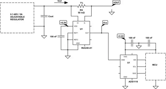
I'm using the following method in one of my power supply designs.

schematic

simulate this circuit – Schematic created using CircuitLab

I'm using this resistor as shunt.

INA240 is a low noise and low-offset current sense amplifier. -A1 version has a voltage gain of 20. So the output of the amplifier will be \$V_{cs} =0.05 [\Omega] \cdot I_{LOAD}[A] \cdot 20 = I_{LOAD-mA} [mV]\$, which means 1mV output per 1mA of IOUT.

In my application, Vcs is about a few tens of μV at no-load. And ADS1118 measures this as very close to zero. I can measure 1mA-5000mA of IOUT with 1mA precision. The accuracy is ±1mA and it is verified with a calibrated Fluke 18B.

The reason that I'm doing high-side measurement is that the customer requested the load to be always grounded even if the power supply is off.

PS: Not an advertisement.

Rohat Kılıç
  • 26,954
  • 3
  • 25
  • 67
0

Well if you're doing it at home I guess this current measurement is not used in a thousand different pieces. A resistor with 0.1% tolerance means if you order a 1 ohm resistor you get 1 ohm +/-0.1%, but if you have the possibility to measure your 1 ohm 1% resistor with an accurracy of +/-0.1%, this gives you the same result.

So why not order an ordinary 1 ohm resistor and determine its actual value by measuring it? Or is a multimeter already part of a "electronic lab"?

Transistor
  • 168,990
  • 12
  • 186
  • 385
po.pe
  • 2,548
  • 1
  • 10
  • 25
  • Honestly, I don't quite understand the point. Plus, note that I need really small resistances for current measurements. One can get 100Ohm 0.1% resistor for a relativelly small price, but not 1Ohm. – Pygmalion Feb 16 '18 at 10:36
  • You could get ten 100 Ohm resistors and parallel them to get 10 Ohms if it works for your project. – Willtech Feb 16 '18 at 10:42
  • Buying a 0.1% tolerance resistor means you know the resistance of it with an accurracy of +-0.1%. You can achieve the same by buying a regular 5% tolerance resistor and measure its value with a multimeter that is at least 0.1% accurate. As I don't know how large your current is, I don't know what resistance range is acceptable. – po.pe Feb 16 '18 at 10:43
  • @Willtech I would need 100 resistors then, because target (upper) resistance is 1 Ohm. – Pygmalion Feb 16 '18 at 10:43
  • @Humpawumpa You cannot measure resistance with 0.1% precision with multimeter... See the last part of my question. – Pygmalion Feb 16 '18 at 10:45
0

Multimeters usually read consistently without much fluctuation so, that is to say, that a particular multimeter will consistently read 12.1v for example on a precisely 12v supply, so it reads a bit high but this only has a small implication to calculations.

The solution may be to grab a bunch of 10% tolerance resistors (either half or double the value that you are seeking) because they are cheap (1% if you like, if your budget allows) and connect two in series onto a power supply. You can then measure the supply voltage, the current, measure the voltage drop across each resistor using your multimeter and calculate the resistance of each resistor comparatively. I presume you will not have too many that are very close to the specified resistance because they would already have been sorted and banded with a closer tolerance but, you should be able to find two resistors to add to get the value that you want either in series or in parallel.

10% tolerance on a resistor does not mean 10% fluctuation during operation, once they are manufactured thy are pretty much fixed.

It is usual in instruments to have a shunt and an adjustment. This also removes the need for your tolerance to be so tight.

Willtech
  • 159
  • 6
  • 1% resistors are cheap enough. I don't think multimeters come even close to 0.1% accuracy. But if the value of resistors follow a Gauss distribution around the nominal value, then yes, buying few dozens and picking the middle ones would give you much better tolerance. But how can I be sure about that? – Pygmalion Feb 16 '18 at 11:06
  • @Pygmalion It is possible to have your multimeter scientifically calibrated and validated. I have no estimate of the cost, only a past verbal reference that there are services that do this. I presume you must have some accurate method of current reading available to calibrate your design once it is implemented. It is usual to have a shunt and an adjustment in multimeters, and probably wise in a circuit design to allow for calibration adjustment. This also removes the need for your tolerance to be so tight. – Willtech Feb 16 '18 at 11:13
  • If I had some lab-grade multimeter, possibly. It is just a home project. What I find curious is that it is easy to achieve 0.05% accuracy for voltage measurement, and it is damn difficult to get beyond 1% for resistors. Makes no sense. – Pygmalion Feb 16 '18 at 11:17