2

am designing a BLDC hub motor (48V-500W-15A max)

I have designed a three phase inverter and the motor run normally with smooth rotation and as the motor start running and I apply the load the motor draw more current and every thing is normal.I am using PWM to control the speed

But the problem is that as I apply a load before the motor start to move even a very small load the motor do not start till we reach a high PWM value then the motor draw a very high current spike it reached a 26A then the motor start rotating at a fairly high speed. we run at 10KHz frequency.

So is there is an issue should I take care with at starting the motor on a load or this is a nature response and The only solution is to use very high rating components,,,
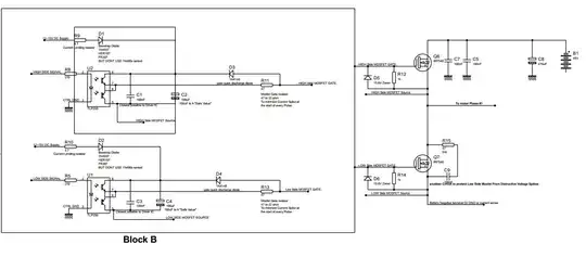
enter image description here

Osama
  • 23
  • 5
  • 1
    Aaaargh! Turn off the grid before taking a screenshot. It's unreadable. – Transistor Feb 12 '18 at 20:20
  • Why do you have bootstrap components on your low side driver? –  Feb 12 '18 at 20:31
  • What type of feedback? – John Birckhead Feb 12 '18 at 20:43
  • @ John Birckhead,, the hub motor has a 3 hall sensors that sense the position – Osama Feb 12 '18 at 20:44
  • @ Brian Drummond,, you are right this bootstrap is not important we worked just fine with or without it.. would this bootstrap make cause this starting problem? – Osama Feb 12 '18 at 20:48
  • High side or low side PWM? – John Birckhead Feb 12 '18 at 20:52
  • @John Birckhead ,, High side PWM with 10Khz frequency the max motor RPM is 400 – Osama Feb 12 '18 at 21:20
  • Sorry to keep asking questions. How fast are you ramping up? – John Birckhead Feb 12 '18 at 21:44
  • John Birckhead I start from 0 PWM and increase it by 1 then make a 30ms delay then increase another 1 and so on till i reach the desired PWM value – Osama Feb 12 '18 at 21:48
  • Sounds like the controller is OK, so I'm betting your ramp is too fast. Your motor is probably good for about 5 ft-lb of torque, and you are trying to accelerate the hub with its moment of inertia. Best would be to measure the current and limit it to 15 A (use current feedback) during spin-up and speed changes. Otherwise you'll have to do the math and change the rate of your ramp depending on motor speed. An easy test is to ramp up very slowly and see what happens to peak current. – John Birckhead Feb 12 '18 at 21:59
  • @John Birckhead,, I used current sensor to limit the current to 15A as follows: i measure the current and when it exceeds 15A I write PWM to be 0 then wait for 50ms then write the desired PWM again and so on ,,I thought this way will solve the problem but what happened is that I had a very fast and rough current ripples and it looks like my 50ms does not affect at all.. and as for the acceleration I reach the full speed from 0 in 600ms or so ,, to what value do you recommend I increase this value? – Osama Feb 12 '18 at 22:15

1 Answers1

1

Actually the BLDC should deliver max torque at 0 rpm, also the max current. There must be a big flaw in your project, could be the synchronism, phase sequence, ....who knows? The information provided is just too little.

PS:

Looking at the schematics, there are a lot of wrong things. Like the diode on the gate signal is placed wrongly. The zener diode at the gate? Why do you need it, to add some extra capacitance, maybe?

Marko Buršič
  • 23,562
  • 2
  • 20
  • 33
  • ,, Thank you for our reply ,, the thing is the motor works fine as long as the motor start moving the only problem is when we put load before starting to move, – Osama Feb 12 '18 at 20:46