Forgive my lack of understanding and if this is answered somewhere I have not found, but... I have seen lots of answers with regard to how to use a darlington pair to switch, say, a 12V 1A load using a 3.3V 50mA signal (just an example, not all values are determined for my application,) but what I'm not clear on is why in the solutions using a darlington pair, the load is always placed on the high side of the transistor(s). While switching the low side is common and functionally fine, in my application, for safety reasons, I would prefer to switch the high side of the load. So, is it ok to put the load on the output of a Darlington Pair Transistor?
Asked
Active
Viewed 1,442 times
1
-
Have you done the math yet? – Ignacio Vazquez-Abrams Feb 05 '18 at 06:52
-
Which math would that be? The question is more of a standard practice thing. – Farkologist Feb 05 '18 at 06:58
-
The math that involves the voltages across and currents through the circuit. – Ignacio Vazquez-Abrams Feb 05 '18 at 06:59
-
That would involve determining/choosing the voltages to be used by the load and to be feed into the base. That hasn't been done. This is purely a standard of practice thing. How can I improve my question to clarify this? – Farkologist Feb 05 '18 at 07:04
-
High side switching vs low side switching: https://electronics.stackexchange.com/questions/188072/difference-between-high-and-low-side-switching-of-power https://electronics.stackexchange.com/questions/251618/high-side-switch-and-low-side-switch https://electronics.stackexchange.com/questions/245603/low-side-and-high-side-switches – Dampmaskin Feb 05 '18 at 07:57
2 Answers
4
For clarification: If you write "put the load to the high side" this means "low side switching".
In the comments section of your question there are a lot of links to the nuts and bolts of high side switching. It shows, how the complexity of high side switching looks like and where the pitfalls are. But why is it more difficult anyway? Can't you put the load simply to the emitter?
Let's compare those two circuits, assuming a forward gain of 1000 for the BJT-Darlington. The first circuit allows up to 0.6 A on the collector in linear mode, as the voltage drop over the base resistor is 0.6V due to the two base voltages adding up to 1.4 V. This won't be reached, because the load only permits a current of 100 mA with the given voltage. The transistors will of course leave linear mode and enter saturation, which is not a real problem in switching application. The actual current through the load is only limited further by the saturation voltage which can be as low as 0.3 V with modern BJTs. So the current might rise up to 97 mA.
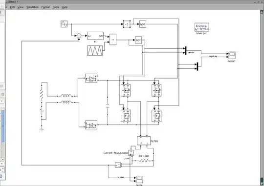
simulate this circuit – Schematic created using CircuitLab
The second circuit won't do what we want. Because the base current enters the node on the upper end of the load, which means for a base current to flow at all, the voltage across the load can't rise above the control voltage minus 1.4 V, which is again only 0.6 V, but this time limiting the whole emitter current to 6 mA. This is probably not, what you wanted to achieve.
Ariser
- 3,846
- 3
- 23
- 43
3
It depends on how well the darlington transistor is heatsinked, and whether its extra voltage drop matters.
When a darlington pair is used with a collector load, the voltage drop is around 1v, that's a VBE of around 0.7v for the first transistor, and a VCEsat for the second.
When a darlington pair is used with an emitter load, the voltage drop is in the range of 1.5v, a VBE for each transistor, and often a bit more depending on how hard they need to be driven. That's assuming the base voltage can be taken all the way to the positive rail. If it can't, and all devices need some drop across them to source current, then that adds directly extra voltage drop to the output. Increased voltage drop means not only lower load voltage, but also increased darlington heating.
There are PNP darlingtons available, so that you can do positive side switching with the load in the collector.
Neil_UK
- 158,152
- 3
- 173
- 387
-
1Thank you Neil. While I don't totally understand that yet, it points me to a few subtleties that I can research and learn about. – Farkologist Feb 05 '18 at 07:12
-
2A slightly different description: For an NPN Darlington, if the load is between emitter and ground, the transistor will be acting as an emitter follower, so the voltage across the load cannot be above the base voltage minus 1.5 V. Similarly, for a normal NPN transistor emitter follower, a load between emitter and ground cannot have more than [base voltage - 0.7 V] across it. – Peter Bennett Feb 05 '18 at 07:52