3

After using Stackexchange for several years now for solving all my Python, LaTeX, math, electronics, engineering and life questions, I have finally come up with a problem I cannot find an answer to. I hope you can point me in the right direction.

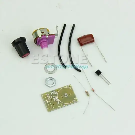
My problem is as follows: I bought two diy dimmer sets for 230VAC, max. 100W (like the one in the picture). Because the Halogen light I want to control is 100W I replaced the triac that came with the package with a BT139 (just to be on the safe side). After putting them both together I noticed that one of the two starts flickering below, say, 50%. I have tried switching the bulbs, switching the wiring order, I measured the potmeters resistance (which is fine), I measured the voltage drop across MT1 and gate (0.412V, which is about the same ass the other triacs), all soldering and wire connections are fine (<1 Ohm). Unfortunately, that is about as far as my knowledge goes. pcb + components

For understanding the circuit, I found a scheme of exact this dimmer here on Stackexchange (the Diac is a 30V one, the triac is a BT139):

circuit, can't find the original stack

Can you guys give me some hints of what I can do?

Thank you!

P.S. I only have a multimeter, I don't have a oscilloscope at my disposal...


Thanks for all the help guys! It appears the solution was really simple: I tried reversed the wiring of the dimmer (again) and miraculously it now stopped blinking... Can anyone of you come up with a theoretical explanation? It would be great to say I did not waste all those hours fooling around, but I actually learned something(:

Dave Tweed
  • 168,369
  • 17
  • 228
  • 393
user176883
  • 31
  • 1
  • 2
    OP this seems like a really bad idea, hooking up a diy kit to mains and high power loads. If you just want a dimmer for your lights, you'd be much better off buying one at the hardware store. $20 is nothing compared to possibly having your house burn down from a shoddy kit. – C_Elegans Feb 03 '18 at 23:14
  • Which Triac is worse? and load can be moved. – Tony Stewart EE75 Feb 03 '18 at 23:27
  • C_Elegans: to be honest, I needed it to be really small and of a specific size, that's why I ended up here. I already have some working PWM dimmers. but those are too large to fit in the casing. Also I (apparently falsely) assumed less components giving less trouble. @TonyStewart.EEsince'75: I'm not sure what you mean, do you mind to clarify? In short: I have two sets, both I replaced the 1A triac with a BT139. Only one of them keeps flickering, the other is doing fine. I will try changing the order of wiring to my bulb. Thanks for the comments! – user176883 Feb 04 '18 at 00:09
  • Use 2 RC time constants like a proper dimmer and it wont flicker badly . – Autistic Feb 04 '18 at 00:10
  • e.g. http://tinyurl.com/y7dvfb55 – Tony Stewart EE75 Feb 04 '18 at 00:39
  • Perhaps @Autistic has a good idea. I have run afoul of flickering incandescent loads because of thermal time constants in an entirely different circuit. I'd guess that halogen bulbs might be less stable than old-fashioned incandescent bulbs. – glen_geek Feb 04 '18 at 03:50
  • Is this a low-voltage (eg. 12V) halogen with a transformer or "electronic transformer" between the dimmer and the bulb? – Spehro Pefhany Feb 04 '18 at 04:21

1 Answers1

1

R2 may have too high of a value, and reversing the parts order only proves something was wrong. The sidac may be damaged if the potentiometer went to zero ohms in your original design, which is the one you should be using.

Right now that capacitor is putting 20 mA into the gate of the triac, through the sidac. Way too much current.

That 2 K resistor is in series with the potentiometer to prevent a 'zero ohm' condition. Put it back the way it was and try another sidac. If it is a sensitive triac make R2 3.3 K. If it needs more drive current drop the potentiometer to 250 K. These circuits are too simple not to work unless something fails or is a miss-match.