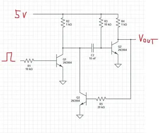
The exercise 2.3 in 3rd ed. of Art of Electronics asks: what is the output voltage during the pulse?
I've replicated the circuit diagram from the book below (in circuitlab.com).
I'd be grateful if someone could read my interpretation below and correct any mistakes:
(A great explanation of the operation of the circuit without Q3 and R5 can be found here. In my question I'm just skipping to the part where circuit is generating the output Vout.)
The Q2 is now OFF, and so R4 and R5 form a voltage divider. A voltage divider with R4 and R5 values (1k and 20k) and 5V input would result in 4.76V output.
However, this circuit does not have 5V dropped between this voltage divider: the base of Q3 will be at 0.6V, which means there is only 4.4V dropped over these 2 resistors.
For 4.4V input, the divider will drop 0.21V across R4 and 4.19V across R5, in order to keep current at 0.21mA. This will put the Vout at (5-0.21 = 4.79V).
The second part of the question asks: What is the minimum required beta of Q3 to guarantee saturation?
This part I don't understand.
With 9.4V (C charged to 5V being pulled to ground by opening of Q1 results in base of Q2 dropping to -4.4V) across R3, there is 0.94mA current flowing though C1.
With 5V across R2, will there also be 5mA flowing through that resistor? Depending whether Q1 is still on (the input to Q1 base is a pulse shorter than the desired output pulse of the circuit), there will be 2 paths for this current to flow (CE of Q1 and CE of Q3).
Assuming Q1 is off, does that mean there will be 5+0.94= 5.94mA flowing through Q3? With 0.21mA flowing into the base of Q3, the minimum beta would only be ~28.
Thanks for responses in advance.
