2

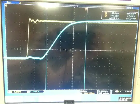
I have this picture (Sorry for the glare): enter image description here

The two verticle bars are a at 0.5v and b at 4.5v, or at least roughly at this spots. I need to get the rise time from 0.5v to 4.5v, but I don't understand the measurements on the top right. is it 100 microseconds? or 124.6 nanoseconds? I'm guessing it is the 124.6 nanoseconds.

Thanks for any help!

JustHeavy
  • 279
  • 4
  • 11
  • the cursors (vertical bars) refer to time, not to voltage (the scope happens to display the voltage when the trace crosses the cursor) ... you would need horizontal bars for voltage levels ... the `Δ` (delta) means `change` (as in "from one value to another") .... so your guess is correct – jsotola Feb 01 '18 at 22:55
  • Just tossing this out there. The rise time is usually measured between the 10% and 90% points on the signal's rising edge, using the flat part of the signal before the step (ignoring any preshoot) as 0%, and the flat part of the signal after the step (ignoring the ringing) as 100%. The signal shown on your display looks like its starting 0% amplitude is ~0 Volts, and its ending 100% amplitude is ~4.5 Volts. So ordinarily you would measure the rise time as the elapsed time (delta t) between 0.45 Volts (10%) and 4.05 Volts (90%). – Jim Fischer Feb 01 '18 at 23:05

2 Answers2

4

The time difference, know as the delta (Δ) is displayed there too. It's 124.6 ns between the markers.

The other times you're seeing are the elapsed time from the trigger point.

Note that the delta often simply translates to "the difference", so it's not specific to time.

Samuel
  • 11,811
  • 31
  • 51
1

To add what @Samuel said...

Looks like time resolution is 40 ns/div and cursors are >3 div separation on X axis and 4 div x 1V/div on Y axis.

Normally rise time is done from 10% to 90% of the steady state and not 10~90% of the ideal output which appears to reduced to 4.6V for some reason. ( source ESR )

Thus I would suggest you consider response time at 10~90% of steady state.

Where f-3dB ~= 0.35/Tr using this method. So leave @ 10% or 460mV and B @ 4.14V which results Δt ~ 80ns. But you can see the impedance must rises with a slower slew rate above 4V like many BJT buffers with low impedance for Vol. SO the next conclusion is the rise time is also controlled by load capacitance and current limit with a linear current slope from 0.1 to 3V giving a linear dV/dt for RC=T asymptote = 80 ns , same as above.
Tony Stewart EE75
  • 1
  • 3
  • 54
  • 182