Note* I have done some searching and though there are related topics to this one, this one is unique and I think it warrants its own Question, especially as asking additional questions on another thread is prohibited.
Measure Battery Current via Shunt
This is sort of similar to my problem but the real question is different.
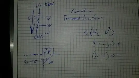
I want to measure current and change it into an analog 0-5 voltage signal. I already have a shunt in place. I think it is 0.5mohms. The current will range from -50amps to +200amps (or even+400 amps is possible in the future). I am only interested in the reverse current. I don't care at all about the positive current. 0amp and +200amps can all output zero. I already have an op amp based circuit for other functions related to this project. All op amps on this circuit have rails set to 0 and 5v. If I was interested in the positive voltage only, I would think I could just put each side of the shunt to the inputs of a differential op amp
So assuming that would work, would it work in the reverse direction? Well of course not, the difference between the two of them is negative, and will rail at 0v. But, if I switch s+ and s- as being input into the opposite inputs of the op amp, then their difference (v2-v1)is positive (-2mV - -4mV).
So in my mind I think that should work, but the real question is, both of the inputs are below the negative rail. I haven't worked op amps with input signals beyond the rails. Is this why my prototype didn't work, or was there a bug that I didn't find?
I also have some understanding that I will be measuring very small voltage drops across this thing. If I want to resolve as low as 5amps on a 0.5mohm shunt, that should be 5a *0.5ohm / 1k = 2.5mV. The input offset of the op amp is 200uV though, so I am assuming I should see an equivalent of 2.3, or 2.7mv difference going into the op amp input, am I mistaken?
If I set the gain to like 200. then for about 50amps in the reverse I should be seeing about 5v as the output of the op amp. 10 amps would be about 1v. For my application it doesn't really matter if the input offset is skewing it a bit. I just need some sort of understanding of the reverse current amplitude. I realize this is a bit of a book; my apologies.
Update1*
I have just built a differential circuit using the same op amp. I gave the rails 0 and 5v, and set the gain to 10. I then varied eac of the inputs randomly between 0 and -1.4v, and took about ten measurements of the inputs and outputs, and I seem to be getting the desired results of G(V2-V1). note* I set r1=r2, and r3=r4 so that the differential op amp equation simplifies down to r2/r1(v2-v1), but anyways. It seems to be working for the voltages I tested, but the input voltages in the tests had a fairly large amplitude compared to what I will be getting off of the shunt. Any ideas?
Update2* So seeing that I can get the correct output for inputs beyond the rails, that means that half of this question is answered. The question remaining is, will this work for inputs as low as -2mv?
I am dubious about it. Here is one of the reasons why. As I was adjusting my negative voltages that were being inputted into the op amp (I was doing this with potentiometers) I would set one to, lets say, -0.5v, and go to adjust the other one. After adjusting the other one I could come back and check the originally -0.5v node only to find that it had shifted to -0.65v. I am getting some instability. I would normally combat this by buffering both of the inputs with a voltage follower before they made it to the subtractor + and - inputs. That, however, is impossible in this case as the voltage follower would simply rail down to 0 and the negative voltages would be lost.
This begs the question, can a simple inverting op amp with the gain of -1 be used as an effective negative voltage follower and give the needed stability to the system without losing the negative input voltages? Any ideas?
Update3* I will try this and see if it works for me. Inverting buffer with op-amps Why should I care if the signal is off by 3%? I don't care so much about the signal differences being exactly to scale. I just need to be able to see it going up and down.
Here is a question. If I answer my question all by myself should I be deleting it or leaving it here for others to learn from?

