I need to build a constant current driver for a LED with a forward voltage of 3.4V and 350mA maximum current. The driver will be controlled by a PWM signal from a 3.3V MCU.
Reading this post and doing the calculations using my system specs, I came up with the following circuit:
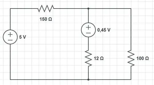
simulate this circuit – Schematic created using CircuitLab
I had to choose a 12V power supply due to the high forward voltage of the LED, which resulted in a minimum power supply voltage of 6.5V. Therefore I couldn't use a 5V power supply.
However, I'm concerned about the power dissipation on the transistor. If my calculations are right, the power dissipated across it would be (neglecting base current and considering Vbe=0.7V):

And the BCP56 can only dissipate a maximum of 1.35W with properly sized mounting pad in the PCB.
First of all I would like to know if the my calculations are right and, in case they are, what would be a good solution.
The only two options I can think of are either picking a beefier transistor that can dissipate more power or reducing the power supply voltage, although I like the idea of using as 12V power supply since it's easier to find locally.
Furthermore, is BJT a good solution for this type of driver or changing for a MOSFET based driver a more suitable option?