1

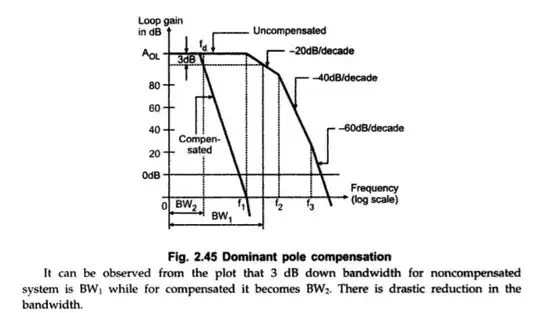
I read that freq. compensation is done to adjust opamp's corner freq. to single one.

A text mentions:

enter image description here ....

Freq. compensation does that i.e reduces corners to one for stability:

enter image description here

But why is an opamp with single corner frequency more stable than the one with two or more corner frequencies?

floppy380
  • 1,715
  • 7
  • 33
  • 67
  • Essentially, it only has one source of phase shift, making it less likely that the phase shift on the negative feedback becomes 180 degrees (and thus positive feedback). But that plot appears to show 3rd order compensation which is ... odd, to me. Where does that figure come from? –  Jan 30 '18 at 14:20
  • The text doesn't say that _all_ circuits with a single corner are stable, but out of the circuits you have so far been presented with, the one with only one corner is stable. – pipe Jan 30 '18 at 14:23
  • @pipe I also was talking about a single opamp. A particular opmap with one and more corner freq. – floppy380 Jan 30 '18 at 14:24
  • @BrianDrummond https://books.google.com/books?id=bmt-l0KgOdsC&lpg=SA2-PA45&dq=op%20amp%20frequency%20compensation%20%22dominant%20pole%20means%22&hl=da&pg=SA2-PA46#v=onepage&q&f=false – floppy380 Jan 30 '18 at 14:28
  • redundant question https://electronics.stackexchange.com/questions/351139/understanding-of-dominant-pole-compensation/351146#351146 – Tony Stewart EE75 Jan 30 '18 at 14:28
  • quoting from the book "the loop gain drops to 0 dB with a slope of -20dB/decade" (OK that's first order) yet the figure clearly shows -60dB/decade. I suspect the figure is garbage, which makes me wonder about the text... –  Jan 30 '18 at 14:29

2 Answers2

2

But why is an opamp with single corner frequency more stable than the one with two or more corner frequencies?

An op-amp with no break (corner) frequency (ideal) produces an open-loop phase shift of exactly 180 degrees in an inverting circuit and is inherently stable with most configurations of feedback resistors/capacitors. However, you can still turn an otherwise ideal op-amp into an oscillator by externally adding two corner frequencies. Externally generated corner frequencies behave exactly the same as internal ones; they each shift phase by 90 degrees and reduce amplitude with frequency at a higher rate.

A single break frequency shifts the open-loop phase response by 90 degrees and this means it still cannot become an oscillator when conventional negative feedback is applied because, for it to oscillate, it requires another 90 degrees to turn negative feedback into positive feedback.

Two break frequencies will inherently produce 180 degrees and quite possibly turn an inverting amplifier into an oscillator. I say this is "possible" and this is true (unless the open loop gain has fallen below unity at the point where the extra phase shift becomes 180 degrees). So you need an open-loop gain greater than unity and an added phase shift of 180 degrees to make an op-amp into an oscillator.

I read that freq. compensation is done to adjust opamp's corner freq. to single one.

Frequency compensation can turn a previously unstable op-amp into a stable op-amp by smothering the open-loop bode plot with a corner frequency that is significantly lower than the original corner frequency in an attempt to ensure that open-loop gain drops below unity before the 2nd corner frequency is reached.

There will still be a 2nd corner frequency (and a third) but they will be at open-loop gains lees than unity. Hence they can't turn an amplifier into an oscillator.
Andy aka
  • 434,556
  • 28
  • 351
  • 777
0

You need to compensate your opamp, which uses the negative feedback path, in order to make it stable, for example to prevent it from oscillating. The opamp itself has its own poles (frequencies where the gain drops by additional -20dB/dec). For example, class A opamp:

class A opamp

has two poles. One at the output and one at the gate of M7 transistor. In order to compensate this architecture you use the Miller technique, that is, capacitor Cc and resistor Rz. Due to the Miller compensation a dominant pole is introduced and the frequency response looks as follows:

frequency response AC

The more phase margin you have, the more stable your opamp is. 90 degrees means you have only one pole (one frequency) before the end of the bandwidth. Other poles (frequencies) are after the bandwidth.

Tako
  • 184
  • 10